Get a Quote
Every time you charge your phone or power up a factory line, a transformer of energy is quietly at work, stepping voltage up or down between circuits. A transformer is a static electrical device that transfers electrical energy from one circuit to another through electromagnetic induction. It has no moving parts. The sole purpose is to change voltage levels without altering frequency, making power distribution both safe and efficient.
Think of a transformer as the universal adapter of the electrical world. On one side, it accepts a certain voltage; on the other, it delivers a different voltage—higher or lower—depending on the winding ratio. This ability to adjust voltage is what allows electricity generated at power plants to travel hundreds of miles over high-voltage lines, then be reduced to a safe level for your home or business.
The core components remain the same across all sizes: a magnetic core, typically made of laminated silicon steel, and two or more windings of copper or aluminum wire. When alternating current flows through one winding, it creates a varying magnetic flux in the core. That flux induces a voltage in the other winding. No physical connection exists between the windings. The transformer of energy thus isolates circuits while transferring power, adding a layer of safety and flexibility that direct connections cannot provide.
From thumb-sized cores in smartphone chargers to units weighing over 100 tons in substations, transformers scale to match the load. The principle never changes—only the physical size and cooling method do. This consistency makes them one of the most reliable pieces of electrical infrastructure, with typical service lives exceeding 25 years when properly maintained.
All transformers operate on Faraday’s law of electromagnetic induction. When alternating current flows through a primary winding, it sets up a time-varying magnetic flux inside the core. That flux links with a secondary winding and, per the law, induces a voltage proportional to the number of turns. The fundamental relationship is simple: the ratio of primary voltage to secondary voltage equals the ratio of primary turns to secondary turns.
Mathematically, Vp / Vs = Np / Ns = Is / Ip. If the secondary has more turns than the primary, the output voltage is higher—a step-up transformer. If it has fewer turns, the voltage is lower—a step-down transformer. The product of voltage and current, or apparent power (VA), remains roughly constant on both sides, minus losses. Real-world efficiency typically falls between 95% and 99%, depending on design and loading.
Losses come from two main sources. Core losses, or iron losses, include hysteresis and eddy currents in the magnetic material. Using grain-oriented silicon steel and thinner laminations reduces these. Copper losses, or I²R losses, result from resistance in the windings and increase with load current. High-efficiency designs incorporate larger conductor cross-sections and amorphous alloy cores, which can lower no-load losses by up to 70% compared to conventional steel.
In an ideal transformer, all magnetic flux links both windings perfectly and there is zero resistance—pure energy transfer. Real devices approach that ideal through precision manufacturing and advanced materials. For instance, amorphous alloy core dry-type transformers achieve exceptionally low no-load losses, making them a go-to choice for distribution grids running at light load for extended periods. The core’s geometry also matters: shell-type and core-type constructions influence impedance and short-circuit strength, factors engineers weigh when selecting equipment for specific applications.
Understanding the working principle demystifies much of power system planning. Voltage transformation reduces current in transmission lines, cutting I²R losses dramatically. Doubling the voltage quarters the line losses for the same power transfer. That is why long-distance grids operate at 110 kV, 220 kV, or even 500 kV—and why transformers are the enablers of modern interconnected networks.
Transformers fall into two broad families based on cooling method: dry-type and oil-immersed. The choice between them hinges on fire safety requirements, installation environment, and capacity. Dry-type units use air or resin encapsulation to dissipate heat. Oil-immersed transformers rely on mineral oil (or less-flammable fluids) that circulates through the windings and radiators, delivering superior cooling and higher power density for a given size.
Dry-type transformers dominate indoor installations, commercial buildings, hospitals, and data centers where fire resistance is paramount. They contain no circulating liquid, eliminating the risk of leaks. Epoxy resin cast coils further improve moisture resistance and mechanic strength. Oil-immersed transformers are more common outdoors in utility substations, industrial plants, and renewable generation sites, where large capacities and lower cost per kVA justify the need for containment and periodic oil testing.
| Feature | Dry-Type | Oil-Immersed |
|---|---|---|
| Typical capacity range | 5 kVA - 25,000 kVA | 50 kVA - 31,500 kVA |
| Cooling medium | Air or epoxy resin | Mineral oil / synthetic ester |
| Fire risk | Low | Moderate to high (requires containment) |
| Installation environment | Indoor, confined spaces | Outdoor, open substations |
| Maintenance complexity | Minimal | Oil sampling, leak checks |
| Initial cost per kVA | Higher | Lower |
Another way to classify transformers is by core material. Conventional grain-oriented silicon steel remains the industry workhorse due to proven performance and cost-effectiveness. However, amorphous alloy cores have gained traction in regions with stringent efficiency regulations. They exhibit magnetic properties that drastically cut no-load losses. A silicon steel transformer might meet S13 or S14 efficiency levels, while an equivalent amorphous design can hit S22, aligning with net-zero carbon targets. When part-load operation is the norm—such as in solar farms that see variable irradiance—the amorphous core's superior magnetization curve pays back the higher upfront cost within a few years.
Specialty designs like epoxy resin cast dry-type transformers combine the safety of dry-type with enhanced protection against dust and humidity, making them suitable for metro stations and offshore platforms. On the other hand, 35kV oil-immersed power transformers serve as the backbone of mid-voltage distribution, stepping down transmission voltage to levels that feed industrial parks, wind farms, and mining operations.
The voltage a transformer of energy handles dictates where it sits in the grid hierarchy. Power generation usually starts at 11 kV or 13.8 kV. Step-up transformers boost that voltage for efficient long-haul transmission, commonly to 110 kV, 220 kV, or 500 kV. At the destination, step-down transformers bring voltage back to distribution levels, typically 35 kV or 10 kV, before final reduction to industrial (480 V, 690 V) or residential (120/240 V in the US, 230/400 V in many other regions) service voltages.
In practical terms, 10 kV transformers form the workhorses of urban and factory distribution. They feed directly into ring main units and switchgear that supply commercial buildings, small factories, and residential high-rises. The 10 kV oil-immersed distribution transformer is a common sight on utility poles and in compact pad-mounted enclosures, balancing cost and reliability across millions of installations worldwide.
At 35 kV, transformers typically serve as substation units connecting regional grids to large industrial loads. They often interconnect with renewable energy plants, where a solar farm’s inverter transformers step up from low voltage to 35 kV for collection networks before another transformer pushes voltage to the transmission level. The size of these units can reach tens of MVA, and they demand robust insulation coordination to handle switching surges.
Selection at each level considers not only voltage but also rated power, impedance, and short-circuit withstand capability. A transformer feeding a mining crusher, for instance, must tolerate repetitive high starting currents without excessive voltage drop, so a lower impedance value may be specified. In contrast, a utility interconnection transformer behind a renewable generator may need higher impedance to limit fault current and protect downstream equipment. These nuances separate a generic transformer purchase from an engineered solution that ensures years of trouble-free service.
Choosing a transformer of energy is rarely about finding the cheapest kVA. Load profile, environmental conditions, efficiency requirements, and future expansion plans all shape the decision. The starting point is always the rated power and voltage. Specify the primary and secondary voltages, frequency (50 or 60 Hz), and the kVA or MVA needed. From there, layer in cooling type, core material, and regulatory standards.
A decision matrix helps weigh the main options side by side. Consider a typical scenario where a plant engineer must choose between a dry-type and oil-immersed transformer for a new production line.
| Criterion | Dry-Type (Epoxy Resin) | Oil-Immersed (Mineral Oil) |
|---|---|---|
| Initial cost | Higher | Lower |
| Efficiency at full load | Comparable | Comparable |
| No-load losses | Lower with amorphous core | Higher typical |
| Fire safety | Intrinsically safe | Requires clearance & containment |
| Installation footprint | Smaller, no oil pit | Larger, needs bund wall |
| Maintenance over 20 years | Low | Moderate (oil changes, DGA) |
| Noise level | Can be higher | Generally lower |
Energy efficiency standards add another filter. In voluntary or mandatory schemes, transformers are classified by letters and numbers—S11, S13, S20, S22, for example—where a higher number indicates lower no-load and load losses. An S22 oil-immersed design with an amorphous core can cut no-load losses by over 60% versus an S11 equivalent. In a 500 kVA transformer running 24/7, that difference can save several thousand dollars in electricity costs over a decade. When total cost of ownership matters more than purchase price, specifying a higher efficiency tier pays off.
Environmental factors matter too. Coastal installations with salt spray demand corrosion-resistant coatings and sealed cable boxes. High-dust environments like cement plants require forced-air cooling with filtered intakes. For underground vaults or platforms, compact american box-type combined transformers combine the transformer and switchgear in one enclosure, reducing on-site work and improving safety. Always check if local codes require specific fire ratings, fluid types (natural ester, silicone), or outdoor enclosures such as european box-type prefabricated substations that integrate transformer, MV and LV gear into a walk-in kiosk.
The selection process itself can be summarized in five steps:
This structured approach avoids oversizing—which wastes energy and money—and under-sizing, which leads to overheating and early failure. A correctly chosen transformer of energy will return its initial investment many times over through reliability and low losses.
Standard distribution and power transformers fulfill most commercial and industrial needs, but several high-demand sectors require tailored designs that stretch conventional specifications. Renewable energy integration, mining operations, and rail traction each impose unique electrical and mechanical stresses that off-the-shelf units cannot reliably handle.
In solar PV and battery energy storage systems (BESS), transformers see bidirectional power flow. A storage transformer must step up DC-converted AC to grid voltage when discharging, then absorb power from the grid during charging, often at high ramp rates. This requires robust insulation, low partial discharge levels, and careful harmonic rating. Station designs frequently favor oil-immersed units for outdoor inverter skids, but dry-type cast-resin transformers excel in containerized BESS where fire risk is critical. Additional specification points include:
Mining transformers face explosive atmospheres, heavy mechanical vibration, and frequent overloads from crushers and conveyors. A transformer of energy for mining must carry flameproof certification (Ex d or Ex e) for underground coal applications and corrosion-proof enclosures for open-pit acidic runoff. Electrical design factors in high starting torque motors with locked-rotor currents up to 6–8 times full load. Selecting a transformer with lower impedance (e.g., 4% instead of 6%) improves voltage regulation under such loads but raises fault current—a trade-off that demands careful coordination with upstream switchgear.
Rail and metro systems introduce a different challenge: shock and vibration from passing trains. Transformers installed trackside or onboard rolling stock must meet stringent mechanical endurance standards. Windings are often vacuum-cast in epoxy to form a solid, monolithic block that resists cracking. Insulation systems use class H (180 degrees C) or higher to cope with confined tunnel thermal conditions. The small footprint and low maintenance of epoxy resin cast dry-type transformers in the 5 to 100 kVA range make them well suited for signaling power supplies and auxiliary services in metro stations.
Each of these sectors proves that a transformer is never a commodity. The right design extracts maximum availability and minimizes lifecycle cost in the specific environment where it must operate.
Even the most robust transformer of energy can develop problems over decades of service. The good news is that most issues announce themselves early through three telltale symptoms: unusual noise, excessive heat, and visible discharge. A quick, systematic check can prevent minor degradation from escalating into catastrophic failure.
Abnormal noise is often the first indicator. A steady 60 Hz (or 50 Hz) hum is normal core magnetostriction. But a loud, rattling buzz or irregular clanking suggests loose core laminations, unclamped windings, or loose magnetic shielding. Tightening core bolts and verifying vibration mounts usually resolves it. If the noise changes with load, suspect loose winding turns; a sweep frequency response test can confirm and localize the defect.
Overheating has several root causes, each calling for a different fix:
Partial discharge and visible tracking on bushings, especially in polluted or coastal environments, erode insulation over time. Regular cleaning and application of silicone compound can suppress surface leakage. If cracks or carbon tracks have formed, the bushing must be replaced. For cast-resin dry-type units, surface cracks in the epoxy invite moisture ingress, which leads to insulation breakdown. A tangential tan delta test or partial discharge measurement during commissioning establishes a baseline for future trending.
While these troubleshooting steps cover the most common field issues, returning the unit to factory for reconditioning or replacement is sometimes the safest choice. A transformer that has suffered a major electrical fault or shows severe oil degradation often carries hidden damage. Investing in a new, efficiency-rated design may deliver both better reliability and lower operational costs compared to repeated repairs.
The transformer of energy remains the silent enabler of modern electrification. Without it, power generation would be localized, long-distance transmission impractical, and renewable integration nearly impossible. Understanding how a transformer works, how to compare cooling methods and core materials, and how to match a unit to a specific application separates a durable installation from a costly misjudgment.
Whether the need is a compact dry-type unit for a high-rise, a high-efficiency amorphous core model for a solar farm, or a mining-rated oil-immersed transformer, the fundamentals remain the same: define the load, choose the right insulation and cooling, and verify compliance with prevailing energy codes. By applying the selection framework and troubleshooting awareness outlined here, engineers and facility managers can make informed decisions that deliver safety, efficiency, and decades of dependable service.
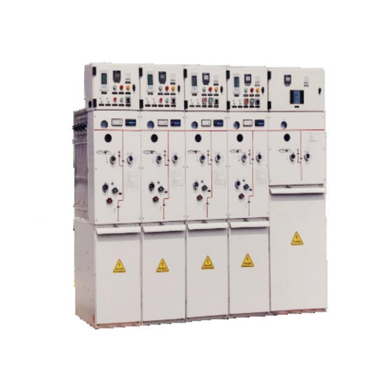
1.Types of High Voltage Switchgear The main categories of high voltage switchgear include Air-Insula...
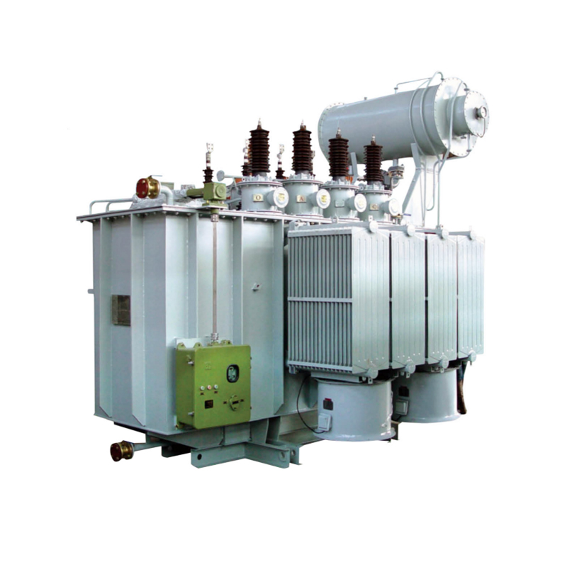
View More1. Working Principle Oil-immersed transformers play a pivotal role in modern electrical power system...
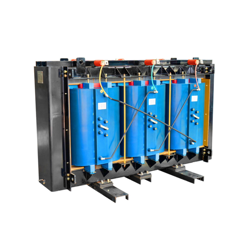
View More1. Advantages of Distribution Dry Type Transformers Distribution dry type transformers have become i...
View More English
 中文简体
中文简体 русский
 Español
 عربى
عربى