Get a Quote
More than 2,000 GW of utility-scale solar capacity operates worldwide, spread across over 100,000 project phases tracked by the Global Solar Power Tracker. That number will jump by a third within a few years, driven by relentless additions in China and India. A solar power plant is the engine behind this shift — an engineered facility that converts sunlight into grid-scale electricity, either by directly exciting electrons in photovoltaic cells or by concentrating heat to drive a conventional turbine.
The technology splits into two main families. Photovoltaic (PV) power stations use semiconductor panels to generate direct current, then step it up through inverters and transformers for grid export. Concentrated solar power (CSP) plants, also called solar thermal plants, deploy thousands of mirrors to focus sunlight onto a receiver, producing steam that spins a turbine. Each route has distinct strengths in sun-rich regions. The table below frames the key contrasts.
| Parameter | PV (Photovoltaic) | CSP (Concentrated Solar Power) |
|---|---|---|
| Core principle | Photovoltaic effect in semiconductors | Mirrors concentrate sunlight onto receiver, generating heat for steam turbine |
| Main components | Panels, inverters, transformers, mounting structures | Heliostats/parabolic troughs, receiver, heat transfer fluid, turbine, thermal storage |
| Typical plant capacity | 1–300+ MW (utility-scale); also small roof-top | 10–250 MW; usually larger and site-specific |
| Best climate | Works in diffuse light; high irradiation preferred | Requires direct normal irradiation >2,000 kWh/m²/yr; arid, clear-sky regions |
| Levelized cost of electricity (LCOE) | $0.024–$0.05/kWh (2026 utility-scale benchmarks) | $0.07–$0.12/kWh; higher but falling with storage |
| Inherent storage | None; must pair with batteries | Molten-salt thermal storage standard; 6–15 hours of dispatchability |
| Grid support | Inverter-based, can provide reactive power with smart controls | Synchronous turbine provides inertia and fault current |
The choice between PV and CSP hinges on more than just cost. In markets that value evening dispatchability, CSP's thermal storage delivers power after sunset without batteries. Still, 95% of new solar installations are PV — the modular, bankable workhorse that dominates from rooftop arrays to 500 MW farms. The rest of this article focuses on PV plants, while pointing out where CSP alternatives remain relevant.
PV and CSP convert sunlight into electricity through completely different physical processes. Understanding how each works clarifies why they suit different scales, climates, and business models.
In a photovoltaic plant, sunlight hits the semiconductor layers inside the panel. Each photon with enough energy knocks an electron loose, creating a direct current. This DC flows to string inverters or central inverters, where it becomes AC. A step-up transformer then raises the voltage — typically from 400–800 V at the inverter to 35 kV for medium-voltage collection lines, and eventually to 110 kV or 220 kV for transmission at the substation. Multiple inverters and transformers are ganged together across hundreds of acres. The only moving parts are sun-tracking motors when single-axis or dual-axis trackers are used.
CSP plants work more like a thermal power station without the fuel. Mirrors — parabolic troughs, linear Fresnel reflectors, or thousands of heliostats around a tower — concentrate sunlight onto a receiver. In a tower system, molten salt or another heat transfer fluid is heated to over 565°C. The hot salt stores thermal energy in insulated tanks; when power is needed, it flows through a heat exchanger to generate steam, drive a turbine, and spin a generator. The plant can run at full load hours after sundown, making it a dispatchable renewable resource. But the optics and thermal cycles demand expert operation and a high direct normal irradiance site.
Both technologies ultimately connect to the grid through a similar medium-voltage collection network and high-voltage substation. In a PV plant, the transformer and switchgear footprint is larger relative to installed capacity because of the distributed inverter layout. In CSP, a central block houses the turbine and main transformer, much like a gas-fired plant.
Solar power plants aren't a single-size product. Developers classify them by capacity, grid connection point, and physical deployment. Each tier has its own economics, regulatory path, and equipment requirements.
Most new capacity is utility-scale ground-mount PV, so the cost and equipment sections that follow concentrate on that archetype. However, the engineering principles scale down to commercial arrays with the right component adjustments.
By 2026, the global benchmark for a 100 MW single-axis tracker PV plant sits between $0.75 and $0.95 per watt DC, while fixed-tilt systems can dip to $0.70/W in competitive markets. The total installed cost per MW varies with location, labor rates, land costs, and module prices — but the percentage split across categories has become remarkably consistent. The table below aggregates real-world project data for fixed-tilt utility-scale PV at three scales.
| Cost category | 1 MW plant | 10 MW plant | 100 MW plant |
|---|---|---|---|
| PV modules & mounting | 35–40% | 38–42% | 40–45% |
| Inverters & transformers | 10–13% | 8–11% | 7–9% |
| Balance of system (BOS): cables, switchgear, monitoring | 12–16% | 11–14% | 9–12% |
| Installation & labor | 15–20% | 12–17% | 10–14% |
| Civil works, site preparation | 6–8% | 5–7% | 4–6% |
| Land & permitting | 4–6% | 3–5% | 2–3% |
| Grid connection & interconnection | 5–8% | 4–7% | 3–5% |
| Development, EPC overhead & contingency | 6–10% | 5–8% | 4–7% |
| Typical total ($/W DC) | $0.95–$1.25/W | $0.80–$1.05/W | $0.70–$0.95/W |
The transformer and switchgear line item might look modest, but it's the spine of the plant's reliability. For a 100 MW site, the main step-up transformer alone can cost $200,000–$400,000. Pair it with ring main units, protection panels, and high-voltage switchgear, and the substation package often approaches 7% of total capex. Skimping on these components invites outages that wipe out years of generation revenue.
When evaluating cost, always tie it to LCOE, not just upfront dollars. A higher-efficiency module or a lower-loss transformer might raise initial cost by $0.02/W but boost annual yield by 1–3%, yielding a positive net present value over 25 years.
A utility-scale PV plant is a chain of energy conversion devices. Each link introduces losses; selecting the right component and sizing it correctly determines the project’s internal rate of return. Below is the core bill of materials and its role.
An often-overlooked item is the earthing and lightning protection system. Large arrays behave like lightning attractors. A mesh of copper-clad rods and surge arresters protects inverters and transformers from transient overvoltages that can punch through insulation in microseconds.
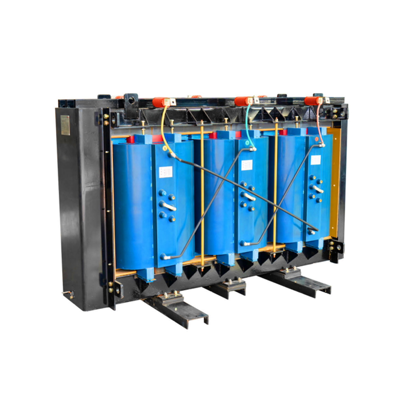
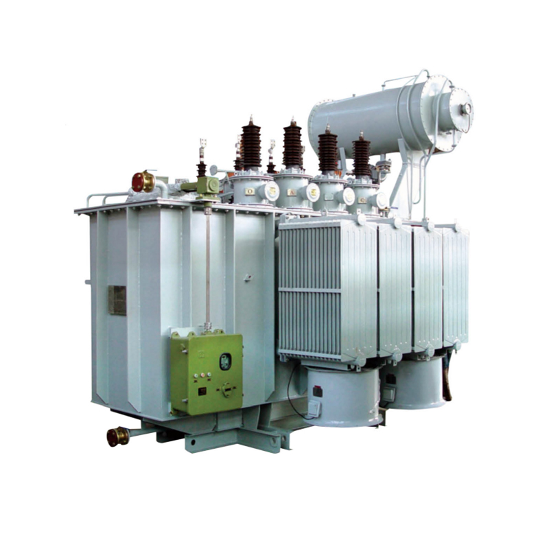
The transformer is not a commodity; it's a tailored decision that directly influences plant losses, fire safety, and long-term maintenance cost. Two main types dominate solar installations: oil-immersed distribution or power transformers and dry-type cast-resin transformers. Each occupies a specific niche.
Oil-immersed transformers use mineral oil or biodegradable ester as coolant and dielectric. They handle overloads well, dissipate heat effectively in outdoor enclosures, and cost 20–30% less than equivalent dry-type units. Their standard IP65 tank, often with corrugated fins, thrives in dusty desert conditions. The trade-off is flammability — a containment bund and regular oil sampling are mandatory. They are the go-to choice for ground-mount PV farms where space and fire risk are manageable.
Dry-type transformers encase windings in epoxy resin under vacuum, resulting in a self-extinguishing, maintenance-free unit with no liquid coolant. They excel in commercial rooftop installations, indoor substations, and high-altitude sites where oil-filled equipment faces permitting hurdles. While their upfront cost is higher and they typically have lower overload margins, modern designs with Class H insulation deliver low partial discharge and can match Tier 2 loss standards. For a 1–3 MW commercial array inside a city building, a dry-type transformer is often the only code-compliant option.
The table below summarizes the key selection parameters.
| Criterion | Oil-Immersed Transformer | Dry-Type Transformer |
|---|---|---|
| Typical installation location | Outdoor pad-mounted or station | Indoor, rooftop, or containerized |
| Fire risk / safety | Class O fluid (mineral oil) requires bund; vegetable oil improves fire point | Self-extinguishing, no oil; preferred near buildings |
| Voltage ratings | Up to 36 kV (common 10, 20, 35 kV) | Up to 36 kV (standard 10, 20 kV) |
| Capacity range | 50 kVA – 31,500 kVA | 5 kVA – 100 kVA (up to 20 MVA with forced air) |
| Losses (no-load + load) | Typically EC Grade 2 (Tier 2); low-loss amorphous core options available | Often meets Tier 2; can achieve Tier 1 with optimized core design |
| Maintenance | Annual oil test, bushing inspection, gasket checks | Visual inspection, IR thermography, cleaning; no liquid maintenance |
| Relative cost | Lower | 20–30% higher for equivalent rating |
Beyond the dielectric medium, the critical engineering parameters are: rated power (kVA) at least 1.1 × inverter AC output; voltage ratio (e.g., 0.69/35 kV); vector group (Dyn11 is standard for inverter duty); impedance voltage (5–8% to limit fault current and accommodate harmonics); and loss capitalisation values. For large solar farms, 35 kV oil-immersed power transformers in the 12.5–25 MVA range feed directly into the grid interconnection substation. Specifying a unit with an amorphous metal core can reduce no-load losses by 60–70%, saving hundreds of thousands of dollars over the plant’s life.
Moving from a land parcel to a commercial operation date requires coordinating engineering, procurement, and construction (EPC) across roughly 12–24 months for a 50 MW project. Tight scheduling of transformer delivery and grid studies is where most delays creep in. The steps below outline a proven sequence.
Throughout construction, a dedicated commissioning engineer should focus exclusively on the transformer and switchgear installation sequence. An incorrectly set tap changer, a missing ground connection, or a loose bushing terminal can cause a transformer failure that sets the project back months.
Over a 25-year operating life, even a well-built PV plant will experience equipment failures. The goal is to detect degradation before it trips protection relays or causes a revenue-generating outage. A structured maintenance plan separates critical planned activities from reactive firefighting.
| Fault type | Typical cause | Average MTTR | Preventive action |
|---|---|---|---|
| Module hot spots & bypass diode failure | Partial shading, cell cracks, manufacturing defect | 4–8 hours (module swap) | Quarterly IR thermography drone scans; replace underperforming modules |
| Inverter tripping on overvoltage or overcurrent | Grid transient, lightning, undersized inverter | 1–4 hours (reset/reconfigure) | Set appropriate grid-protection parameters; install surge arresters on AC and DC sides |
| Transformer overheating or low oil level | Sustained overload, blocked radiator, gasket leak | 2–8 hours (top-up oil, clean fins) | Monthly visual inspection of oil level, temperature gauges; annual dissolved gas analysis (DGA) |
| MV switchgear SF6 gas leakage (gas-insulated) | Seal deterioration, mechanical shock | 4–12 hours (recharge or replace) | Quarterly gas pressure check; alarm thresholds set to 85% of nominal density |
| Cable insulation breakdown | Water ingress in joints, rodent damage, overheating | 6–24 hours (locate and re-joint) | Annual insulation resistance tests; keep cable trenches drainage clear |
| Tracking motor/torque tube failure | Gear wear, wind gust overload, control board fault | 4–12 hours (manual stow, replace actuator) | Monthly mechanical inspection of motors and limit switches; lubricate per manufacturer schedule |
Transformer-specific maintenance deserves emphasis. A large oil-immersed unit holds thousands of liters of insulating fluid. A single internal arc or a moisture ingress event can destroy a transformer in seconds. Annual oil dielectric breakdown tests and furan analysis predict paper insulation aging. Likewise, dry-type units need infrared scans at full load to spot loose connections and excessive coil heating. Re-torquing bolted joints after the first year of operation prevents hot spots.
Many fleet operators now supplement periodic inspections with continuous online monitoring. Dissolved gas-in-oil monitors, partial discharge sensors, and bushing capacitive taps feed data to a central SCADA. When the acetylene level spikes, the system flags a potential arc fault before the Buchholz relay even triggers. That early warning can mean the difference between a $10,000 repair and a $200,000 replacement.
1.Types of High Voltage Switchgear The main categories of high voltage switchgear include Air-Insula...
View More1. Working Principle Oil-immersed transformers play a pivotal role in modern electrical power system...
View More1. Advantages of Distribution Dry Type Transformers Distribution dry type transformers have become i...
View More English
 中文简体
中文简体 русский
 Español
 عربى
عربى