Get a Quote


Walk through the financial district of any megacity and you are likely standing above a substation you will never see. Beneath the sidewalks, sealed in compact metal enclosures, high-voltage equipment operates silently — no exposed conductors, no humming busbars visible to the public. That is a gas insulated switchgear (GIS) substation at work. A GIS packs circuit breakers, disconnectors, and busbars into grounded aluminum housings filled with an insulating gas, squeezing an entire switchyard into roughly one‑tenth the footprint of a conventional air‑insulated station. This density transforms where and how utilities and industrial plants can build substations, opening space‑constrained urban basements, offshore platforms, and extreme environments that air‑insulated technology simply cannot serve.
Engineers evaluating GIS quickly encounter two critical decisions: which insulating medium to specify and how to weigh upfront capital against decades of operating cost. The answers have shifted dramatically in the last five years as regulatory pressure on sulfur hexafluoride (SF6) has accelerated the arrival of low‑carbon alternatives. This article dissects the architecture, economics, and selection logic of GIS substations, giving you a quantitative framework to compare options and avoid the cost traps that catch teams who treat GIS as just a “smaller outdoor yard.”
A gas insulated switchgear (GIS) substation is a compact, metal‑enclosed high‑voltage assembly in which all primary power‑carrying components are housed inside sealed, ground‑potential enclosures filled with a dielectric gas — historically SF6, and increasingly with fluoronitrile‑based or clean‑air mixtures. Unlike air‑insulated switchgear (AIS), where bare conductors sit on porcelain insulators in open air, GIS isolates every phase and component inside a grounded aluminum shell that acts as a Faraday cage. The result is a substation that can operate at ratings from 72.5 kV to 1,200 kV with a failure rate typically below 0.1 faults per bay per year, while occupying about 10–20 % of the real estate required by an equivalent AIS installation.
Inside a single GIS bay, the following core elements are arranged in a modular, flange‑connected sequence:
All these components are factory‑assembled into transportable modules, pressure‑tested, and shipped with the insulating gas at slightly above atmospheric pressure. On site, modules are bolted together with O‑ring sealed flanges, drastically reducing the traditional construction schedule that plagues outdoor air‑insulated yards.
Selecting between GIS and AIS is not a matter of “better” but of fit. The decision turns on five measurable dimensions that reveal where the premium paid for GIS delivers genuine project value — and where it becomes an over‑engineered choice.
| Parameter | GIS Substation | AIS Substation |
|---|---|---|
| Land area footprint | 10–20% of equivalent AIS | 100% (reference) |
| Maintenance interval (major) | 10–15 years | 4–6 years |
| Typical failure rate | <0.1 faults/bay·year | 0.3–0.6 faults/bay·year |
| Environmental tolerance | Indoor/underground/offshore; immune to salt, dust, and moisture | Outdoor only; requires insulation coordination for pollution |
| Installation cycle (110 kV, 4 bays) | 4–6 months (including civil works) | 10–14 months |
The footprint advantage is often the decisive factor. A 145 kV, four‑bay GIS can fit inside a 12 m × 6 m room, while the same functionality in AIS might require a 50 m × 40 m yard. In cities like Singapore or Tokyo, where land cost exceeds $20,000 per square meter, the civil works savings alone frequently pay for the entire GIS premium. Further, because GIS is enclosed, it eliminates the safety clearance zones mandated for live AIS conductors, allowing it to be integrated directly into buildings or placed beneath public parks.
Reliability differentials compound over time. While AIS components such as disconnect switches, insulators, and busbar supports are exposed to airborne contaminants that cause tracking and flashovers, GIS internals remain in a controlled, dry environment with near‑constant gas density. This translates into four‑ to five‑times fewer forced outages, a metric that matters enormously for transmission‑connected wind farms or industrial plants where a single unplanned trip can cost $100,000–$500,000 in lost production.
For decades, SF6 was the undisputed dielectric workhorse. It possesses an insulation strength roughly three times that of air at the same pressure and excellent arc‑quenching properties. The chemistry problem, however, is severe: SF6 has a 100‑year global warming potential (GWP) of 23,900, making it the most potent greenhouse gas ever evaluated by the IPCC. A single kilogram of SF6 released into the atmosphere is equivalent to 23.9 tonnes of CO2. This has propelled a regulatory wave — from the European F‑gas Regulation to the U.S. EPA’s proposed phase‑down — that is fundamentally reshaping GIS procurement.
The market now offers three viable alternative gas families:
| Insulating Medium | GWP (100‑yr) | Dielectric strength relative to SF6 | Minimum operating temp. | Retrofit compatibility |
|---|---|---|---|---|
| SF6 | 23,900 | 1.0 (reference) | −40°C (with heating) | Existing equipment |
| Fluoronitrile‑CO2 mixture (g³) | <1 | 0.95–1.0 at 7 bar | −30°C (C4‑FN blends) | New designs; few retrofit kits |
| Clean air (technical air: 80% N2, 20% O2) | 0 | 0.35–0.40 at 7 bar | −50°C | New designs; larger enclosures required |
| C4‑FN / CO2 / O2 ternary mixtures | <500 | 0.85–0.95 at 6–8 bar | −25°C to −30°C | Some 145 kV retrofits available |
The trade‑offs are real. Fluoronitrile‑based solutions (g³) match SF6’s insulation performance at moderate pressures but require slightly larger tank volumes for equivalent thermal interruption capacity. Clean air eliminates global warming risk completely but delivers only about 40% of SF6’s dielectric strength, forcing a significant physical upsizing — sometimes 20–30% larger enclosures — that erodes the space advantage GIS is purchased for. The practical sweet spot for many new urban installations is a ternary C4‑FN mixture that keeps GWP under 500 while maintaining compact dimensions, especially for voltage levels through 170 kV. Above 300 kV, the industry still leans heavily on SF6 because of unmatched arc‑quenching performance, though pilot installations at 420 kV with clean‑air breakers are now operational.
If your project falls under a jurisdiction with an active SF6 phase‑down schedule, the choice is no longer purely technical — it is a permitting condition. California’s SF6 phase‑out for new GIS under 145 kV took effect in 2025, and similar mandates are spreading across the EU and parts of Asia.
Each GIS bay is a serial arrangement of standardized flanged modules. Understanding what sits inside those polished aluminum cans helps you specify equipment correctly — and troubleshoot when something goes wrong. While configurations vary by voltage and manufacturer, the basic building blocks are consistent.
The breaker is the heart of the bay. Modern GIS breakers use single‑pressure SF6 puffer or self‑blast interrupters that extinguish the arc within 2–3 cycles. A typical 145 kV GIS breaker handles 40 kA short‑circuit current and fits in a housing about 3 m long and 1 m in diameter. The operating mechanism — spring‑spring or hydraulic‑spring — sits in a separate, accessible compartment outside the gas zone.
Many GIS designs integrate a three‑position switch that combines line disconnection and earthing in a single moving‑contact assembly. This eliminates one complete gas compartment and reduces mechanical linkages. Motorized operation is standard for remote interlocking; a manual emergency handle is always included.
Busbars are typically three‑phase, enclosed in a single large‑diameter enclosure or run as isolated‑phase tubes. Cast‑resin spacers provide both insulation and mechanical support. Because busbars run the full length of the substation, their gas volume is large, making leak‑tightness and density monitoring critical. A single flange leak can cascade into a system‑wide low‑pressure alarm.
Ring‑type current transformers slip over the high‑voltage conductor inside the gas compartment, wired to secondary terminals in a separate, accessible marshalling box. Voltage transformers are either inductive (cast‑resin) or capacitive‑divider types, increasingly being replaced by compact resistive‑capacitive dividers that eliminate ferroresonance risk.
The transition from gas‑insulated bus to external XLPE cable or overhead line is handled by a gas‑impregnated epoxy bushing or a gas‑filled cable termination compartment. This is the most failure‑prone interface in a GIS because it involves a dielectric junction between two insulating media. Proper field assembly torque and cleanliness protocols here are non‑negotiable.
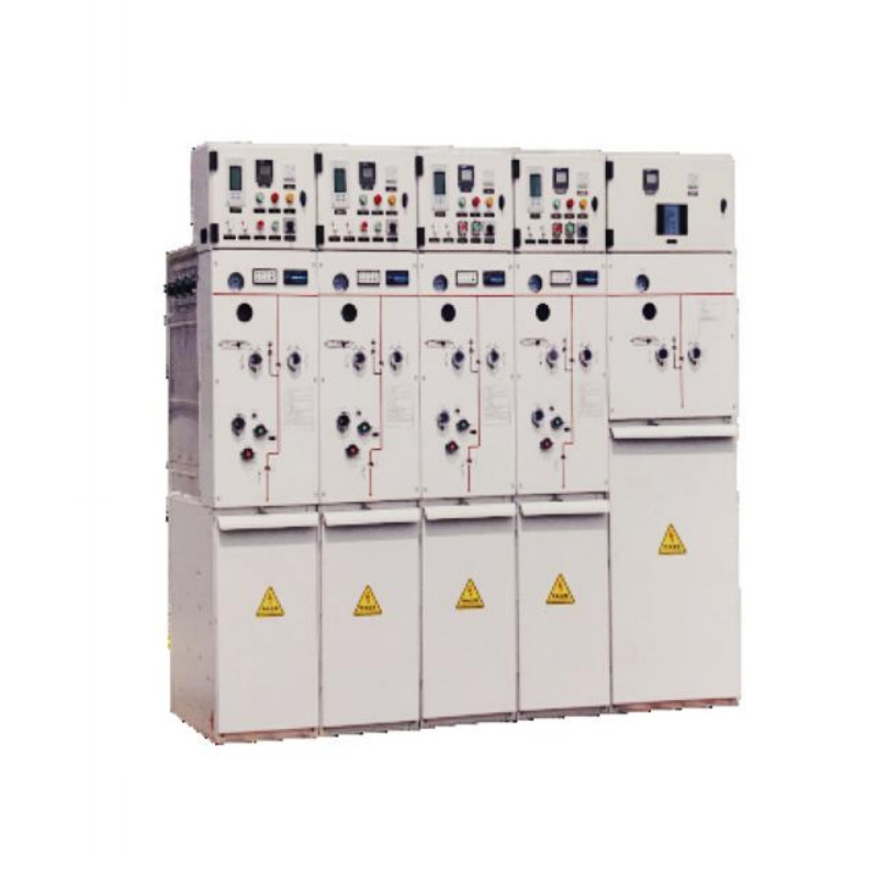
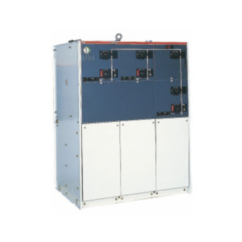
For distribution‑class voltages (12–40.5 kV), a form of GIS known as a gas‑insulated ring main unit condenses all these functions into a single tank, often with C4‑FN gas mixtures to meet low‑GWP targets. The same sealed‑for‑life philosophy applies, scaled down to fit inside a standard 19‑inch rack footprint.
GIS is not the universal answer. When a greenfield site offers abundant, inexpensive land with clean air and low seismic risk, AIS often wins on total cost. However, the equation flips decisively in three scenarios where GIS pays for itself through avoided civil costs, regulatory compliance, or operational continuity.
Cities like London, Shanghai, and New York have been burying substations for 30 years. A 220 kV GIS can be installed 20–30 m below grade with a ventilation shaft as the only visible surface structure. Land savings of $15–30 million at urban land prices are common, and the Faraday‑cage enclosure eliminates electromagnetic interference to nearby buildings. Gas‑insulated substations also suppress audible noise below 65 dB(A) at 10 m, meeting strict municipal noise ordinances without costly acoustic enclosures.
Salt spray, high humidity, and limited deck space make open‑air switchyards impractical offshore. A 72.5 kV or 145 kV GIS fits in a standard container‑sized module, is corrosion‑proofed (Al‑Mg alloy enclosures with epoxy paint), and withstands accelerations up to 0.5 g in platform motion. The sealed gas compartments also prevent moisture ingress, which is the leading cause of insulator flashover in marine environments.
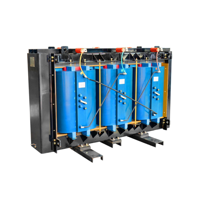
Above 3,000 m, air density drops enough to reduce AIS insulation clearances, forcing larger and larger phase spacing. GIS is immune to altitude derating up to 4,500 m because the internal gas pressure is independent of external atmosphere. At the other extreme, in regions where winter temperatures plunge below −40°C, SF6 or clean‑air GIS with tank heaters maintains reliable operation while AIS bushings risk cracking and mechanical linkages freeze. A dry‑type transformer paired with a heating‑equipped GIS substation forms a fully indoor, cold‑climate solution that requires no liquid‑filled cooling systems.
Purchase price comparisons mislead because they ignore the 30‑ to 40‑year operating life of a substation. A GIS costs roughly 2–3 times more per bay upfront than an equivalent AIS bay, yet the total cost of ownership often reverses by year 10–12 when land, maintenance labor, and forced‑outage penalties are included. Breaking down the cost structure reveals where the money goes and when the payback occurs.
A typical 145 kV GIS bay (breaker + disconnector + CT + VT) has a capital expenditure (CapEx) split of:
Air‑insulated equipment is cheaper to buy but demands a much larger yard, extensive steel structures, and more cabling — civil works alone can be 40–50% of total installed cost. When prime land carries a price, the GIS building can be a fraction of the AIS yard cost even with the higher equipment premium.
The operational expenditure (OpEx) comparison is equally stark. A 10‑year TCO model for a 110 kV, four‑bay substation yields the following:
| Cost Category | GIS (indoor) | AIS (outdoor) |
|---|---|---|
| Equipment + installation | $1,200,000 | $550,000 |
| Land + civil works | $180,000 (150 m²) | $600,000 (2,000 m²) |
| 10‑year maintenance (labor + materials) | $90,000 | $280,000 |
| 10‑year gas handling + leakage make‑up (SF6) | $45,000 | N/A |
| Expected forced outage cost (1 outage @ avg. $150k) | $15,000 (0.1 probability) | $90,000 (0.6 probability) |
| Total 10‑year TCO | $1,530,000 | $1,520,000 |
In this normalized scenario, the total cost is virtually identical by year 10, and GIS pulls ahead in every subsequent year because its maintenance curve is nearly flat while AIS maintenance costs rise as porcelain insulators and disconnect contacts age. When land in urban areas is priced at $5,000/m² or more, the crossover point shifts to year 3–4. Procurement teams that evaluate only the equipment bid price routinely make the wrong long‑term decision.
A GIS arrives on site as a set of clean, factory‑tested modules. The quality of field installation determines whether it maintains its 25‑year design life or develops a chronic leak within the first six months. Following a disciplined sequence prevents the top two killers of GIS reliability: particle contamination and flange joint leakage.
Once in service, the primary maintenance task is gas density monitoring. Each compartment is equipped with a temperature‑compensated density monitor that sends an alarm at the first‑stage low‑pressure threshold and trips the affected bay at a second, lower threshold. An annual visual check of density gauge readings and a five‑yearly PD survey using UHF sensors embedded in the enclosure are the standard predictive practices. Leak rates below 0.1% per year are achievable with modern O‑ring flange designs; any bay exceeding 0.5% per year should be scheduled for leak location using infrared detection or soap‑film testing and resealed during the next scheduled outage.
Selecting a GIS is a multi‑dimensional decision that can be distilled into a structured matrix. Avoid the trap of copying a neighbor’s specification; regional environmental conditions, local gas regulations, and short‑circuit levels differ enough to invalidate a generic selection. Start with the electrical requirements and layer on constraints.
| Parameter | Option A – Standard GIS | Option B – High‑Capacity GIS | Option C – Eco‑GIS |
|---|---|---|---|
| Voltage class | 72.5–170 kV | 220–420 kV | 72.5–170 kV |
| Rated busbar current | 2,000–3,150 A | 4,000–6,300 A | 2,000–2,500 A |
| Rated short‑circuit current | 31.5–40 kA | 50–63 kA | 25–31.5 kA |
| Indoor/outdoor | Indoor (building or container) | Indoor (dedicated hall) | Indoor preferred |
| Environmental constraint | Standard SF6 (permits in place) | SF6 (performance‑critical) | GWP <1 required; SF6 banned |
| Typical typical bay footprint | 1.2 m × 3 m (per bay) | 1.5 m × 5 m (per bay) | 1.4 m × 3.2 m (per bay) |
For most commercial and industrial applications through 145 kV, Option A fits the bill and offers the widest selection of proven designs. Projects that exceed 200 kV or require short‑circuit ratings above 40 kA naturally push into Option B territory, where SF6 still dominates because of its superior arc‑quenching capability. Option C is rapidly becoming the default for any project in a jurisdiction with an active SF6 phase‑out or for owners with an internal carbon‑price mechanism applied to GHG emissions. Many high‑voltage switchgear manufacturers now offer a parallel eco‑GIS product line at 72.5–170 kV, so lead times are competitive with conventional units if you specify the alternative gas early in the bidding cycle.
The final selection step is always a factory visit to witness the partial discharge and leakage tests on your specific bays. No data sheet substitutes for watching the PD screen stay below 2 pC at 1.2 times rated voltage — that single measurement is the best predictor of a substation that will operate 15 years without an internal fault.
1.Types of High Voltage Switchgear The main categories of high voltage switchgear include Air-Insula...
View More1. Working Principle Oil-immersed transformers play a pivotal role in modern electrical power system...
View More1. Advantages of Distribution Dry Type Transformers Distribution dry type transformers have become i...
View More
 中文简体
中文简体 русский
 Español
 عربى
عربى