Get a Quote
In 1966, the first high-voltage gas insulated substation went live in Plessis-Gassot, France, at 245 kV. Six decades later, gas insulated systems form the backbone of power delivery in dense cities, offshore wind farms, and industrial mega-projects. A gas insulated system—most commonly a gas insulated switchgear (GIS)—is a compact substation technology that houses all high-voltage components inside sealed metal enclosures filled with an insulating gas.
Instead of air as the main dielectric, the system uses pressurized sulfur hexafluoride (SF₆) or an alternative gas to achieve exceptional insulation strength in a fraction of the space. Every live part, from busbars to circuit breakers, stays fully enclosed, which eliminates exposure to dust, salt, and moisture. That single decision shrinks the required footprint to just 10–20% of an equivalent air insulated installation.
A gas insulated system delivers the same power rating as a conventional outdoor yard inside a space smaller than a tennis court. This density makes GIS the default choice wherever land is scarce or where permitting a sprawling Air Insulated Substation (AIS) is impossible.
The secret lies in the insulating gas. SF₆ has a dielectric strength roughly 2.5 to 3 times that of air at the same pressure. It also possesses exceptional thermal conductivity and arc-quenching properties, allowing circuit breakers to interrupt fault currents thousands of amps strong inside a tiny gap. Because the conductor-to-earth clearance can be drastically reduced, the entire substation collapses into a series of metal-clad compartments.
Inside a sealed chamber, live parts sit millimeters apart instead of meters. Under normal operation, the pressurized SF₆ simply insulates. When a fault occurs, the circuit breaker’s contacts separate, and the arc forms in the SF₆ environment. The gas rapidly absorbs the arc energy, cools the plasma, and extinguishes the fault within one or two power cycles—roughly 20–40 milliseconds.
A step-by-step breakdown of a typical fault interruption cycle:
This entire sequence completes without any external arc flash or gas venting to the atmosphere. All arc by-products remain contained, and the sealed pressure system prevents moisture ingress, so internal components stay clean for decades.
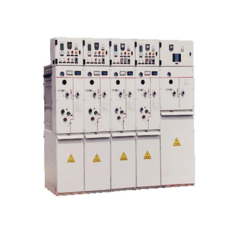
A GIS bay is a modular unit that replicates one feeder position in a substation. While exact layouts vary by voltage and manufacturer, every bay contains a standardized set of primary equipment interconnected inside gas-tight compartments. This modularity allows complete factory assembly and testing before shipment.
| Component | Function | Typical specification / note |
|---|---|---|
| Circuit breaker | Interrupts fault and load currents | SF₆ puffer or self-blast design; rated up to 63 kA short-circuit breaking current |
| Disconnector (isolating switch) | Provides visible isolation gap for maintenance safety | Motor-operated or manual; integrated into the same gas compartment as the earthing switch |
| Maintenance earthing switch | Earthing isolated sections for safe access | Often interlocked with the disconnector; capable of carrying rated short-time current |
| High-speed earthing switch | Rapid earthing to clear trapped charges or induced voltages | Closing time typically under 60 ms; designed for frequent operation |
| Current transformer (CT) | Measures line current for metering and protection | Cast-resin or foil-type inside GIS; multiple cores for different accuracy classes |
| Voltage transformer (VT) | Steps down voltage for protection and control | Inductive or capacitive type; inserted via a gas-tight bushing |
| Busbar system | Distributes power between bays | Three-phase encapsulated or single-phase; rated up to 4,000 A continuous |
| Cable sealing end or SF₆-to-air bushing | Connects the GIS to external cables or overhead lines | Gas-to-air transition interface; manages electrical stress at the termination |
Each compartment is individually monitored for gas density and moisture. If a leak develops in one bay, the rest of the substation continues operating unaffected. This compartmentalization is what makes GIS so resilient—faults stay local. A bay can even be expanded or replaced without draining gas from neighboring sections.
The debate between gas insulated and air insulated substations is not about which is “better” in absolute terms—it is about which technology fits the project’s constraints. AIS remains the economic choice for greenfield sites with abundant land, while GIS dominates in space-constrained or harsh-environment applications.
The table below quantifies the differences on the most decisive factors.
| Parameter | Gas Insulated System (GIS) | Air Insulated Substation (AIS) |
|---|---|---|
| Footprint | 10–20% of an equivalent AIS | 100% baseline |
| Reliability (MTBF) | Typically 2–3× higher due to sealed environment | Lower; exposed to contamination, wildlife, and weather |
| Maintenance frequency | Visual inspection every 1–3 years; major overhaul at 20–25 years | Annual inspections; cleaning and mechanical checks every 2–4 years |
| Installation duration | Weeks; pre-fabricated modules reduce civil works | Months; extensive civil engineering and busbar assembly on site |
| Initial equipment cost | Higher, often 30–50% more than AIS equivalent | Lower; hardware itself is less expensive |
| Total cost of ownership (25‑year view) | Comparable or lower; land savings and reduced maintenance offset higher capex | Can rise significantly if land acquisition and O&M costs are high |
| Environmental tolerance | Excellent; unaffected by altitude, salinity, or industrial pollution | Requires derating in high altitude or polluted areas; additional clearance needed |
Many utilities now run financial models that weigh GIS’s higher upfront price against decades of lower operating expense. In urban cores, the land-cost saving alone can make GIS the only viable option. Offshore wind connections, mountain hydropower plants, and data-center feeds lean heavily toward GIS for the same reason.
SF₆ is an almost perfect insulating and arc-quenching gas—except for one uncomfortable number: its global warming potential (GWP) of approximately 23,500 over 100 years. That reality has pushed regulators worldwide to phase down SF₆ use, starting with medium-voltage equipment and gradually moving toward high-voltage applications. The European Union’s F‑Gas regulation and proposals in the United States and Japan are reshaping the GIS landscape.
Two leading alternatives have emerged: clean air (a mixture of nitrogen and oxygen, GWP = 0) and fluoronitrile-based gas mixtures (such as C₄F₇N blended with CO₂), which reduce GWP by roughly 98% compared to SF₆ while preserving most of the insulation strength.
| Gas type | GWP (100‑year) | Insulation strength vs. SF₆ | Minimum operating temp. | Commercial maturity (HV GIS) | Regulatory outlook |
|---|---|---|---|---|---|
| SF₆ | ~23,500 | 1.0 (baseline) | −40 °C | Fully mature, all voltage levels | Being phased down; new F‑Gas limits apply |
| Clean air (N₂/O₂) | 0 | 0.3–0.4 (requires higher pressure) | −50 °C | Proven up to 72.5 kV; expanding to 145 kV | No restrictions; preferred for “green” projects |
| Fluoronitrile/CO₂ (C₄F₇N mix) | ~300–600 | ~0.95 (with modest pressure increase) | −25 °C to −30 °C | Available up to 420 kV; growing installed base | Compliant with current F‑Gas quotas; future restrictions under discussion |
For medium-voltage distribution, the shift is already mature. Many operators deploy eco-friendly gas-insulated ring main units that use clean air or a solid-insulation approach, eliminating SF₆ completely from the network. At the high-voltage level, more than a dozen utilities now operate pilot 145 kV and 245 kV SF₆‑free GIS bays, and the trend is accelerating.
The choice between SF₆ and an eco-alternative is now a design decision, not a technical impossibility. Projects that must comply with green certification programs or anticipate tightening cap‑and‑trade costs increasingly default to SF₆‑free GIS, even when it adds a few percent to the upfront price.
Selecting a GIS configuration starts with three non‑negotiable parameters: voltage level, available footprint, and the regulatory environment. Every other criterion—cooling, arc rating, busbar current—represents an engineering optimization, not a showstopper.
Use the following checklist to narrow the options:
For medium‑voltage projects that cannot tolerate SF₆, solid-insulation intelligent ring main units provide a maintenance‑free, fully enclosed switchgear option that fits into extremely tight secondary distribution spaces. When the project spans multiple voltage levels, a combined scope—transformer plus GIS—often simplifies interfaces and after‑sales support.
The optimum choice almost never comes from a single data point. Align your electrical, civil, and environmental teams early, and run a 25‑year net present value calculation before locking in a topology.
GIS installation demands precision and a clean environment. Even microscopic particles inside a gas compartment can trigger partial discharge that erodes insulation over time. Therefore, assembly areas must be dust‑controlled, and joints must be tightened with a calibrated torque sequence.
Once in service, maintenance centers on passive monitoring rather than hands‑on intervention. The primary health indicator is gas density, which is continuously tracked by temperature‑compensated pressure sensors. A steady drop triggers a low‑level alarm; a rapid decrease initiates an automatic lockout or trip.
Safety rules are non‑negotiable because SF₆ decomposition products formed during arcing are toxic. Key practices include:
Adhering to IEC 62271‑203 and the manufacturer’s specific instructions covers the technical baseline. What separates a safe operation from a safety incident is the consistent discipline to treat every gas compartment as a sealed, potentially hazardous enclosure—no matter how routine the task appears.
Gas insulated systems have moved from a niche high‑voltage concept in the 1960s to the universal solution for compact, resilient power infrastructure. Whether you need a 12 kV ring main unit in a shopping mall or a 550 kV bay on a floating substation, the fundamentals remain the same: enclose, insulate, and protect.
Selecting between SF₆ and an eco‑friendly alternative is no longer a philosophical debate—it is a calculation of GWP allowances, operating temperature range, and total lifecycle cost. As the industry continues to innovate, expect the boundary between “economical” and “green” to keep moving, making gas insulated systems even more central to every modern grid blueprint.
Explore our gas-insulated switchgear portfolio to see how modular, factory‑tested bays can accelerate your next substation project.
1.Types of High Voltage Switchgear The main categories of high voltage switchgear include Air-Insula...
View More1. Working Principle Oil-immersed transformers play a pivotal role in modern electrical power system...
View More1. Advantages of Distribution Dry Type Transformers Distribution dry type transformers have become i...
View More English
 中文简体
中文简体 русский
 Español
 عربى
عربى