
Get a Quote


Harmonic distortion is one of those power-quality problems that rarely announces itself. Motors run a little hotter, neutral conductors carry more current than expected, capacitor banks fail early, and electronic equipment trips for reasons that are not immediately obvious. By the time someone asks about harmonic distortion mitigation, the symptoms have often been developing for months.
Mitigation is rarely a single product or a one-line fix. It is a sequence of measurement, system design, equipment selection, and commissioning. The good news is that the problem is well understood, and most installations can be brought back to a stable condition without replacing the entire distribution system.
Non-linear loads draw current in short pulses rather than smooth sinusoidal waves. Variable frequency drives, rectifiers, uninterruptible power supplies, LED drivers, arc furnaces, and many types of office and factory equipment all contribute. The resulting current waveform contains frequencies that are multiples of the fundamental supply frequency. Those extra frequencies are the harmonics.
The most common measure is total harmonic distortion, or THD. A high THD figure is a warning, but it is not a diagnosis. The order of the harmonics, the impedance of the supply, and the location of the load all matter. A fifth-harmonic problem behaves differently from a high-frequency ripple issue, and the mitigation equipment must match the actual spectrum.
Left alone, harmonic distortion increases transformer and cable losses, heats windings, stresses insulation, overloads neutral conductors in three-phase four-wire systems, and can cause capacitor banks to fail. It may also produce nuisance breaker trips, inaccurate metering, and audible noise. The cost is not only energy loss; it is reduced equipment life and unexpected downtime.
Before selecting a filter or a reactor, record the system. A power quality analyzer should log voltage and current harmonics at the point of common coupling and at the main feeders that serve the non-linear loads. Capture a full production cycle if possible, including weekends and shift changes. Harmonic levels often change with loading, and a single spot reading can be misleading.
Use the survey to identify the dominant harmonic orders, the existing power factor correction, the transformer impedance, and any resonance risk. A capacitor bank that looks harmless on a sinusoidal system can amplify a harmonic current and create a serious overvoltage condition. This is why harmonic distortion mitigation should begin with a study rather than a catalogue order. For a broader look at symptoms and causes, our article on power quality issues in industrial plants walks through the common patterns.
There is no universal best method. Passive filters, reactors, active compensators, and improved transformer specification each solve a different part of the problem. The table below compares the practical options without pretending that one row applies to every site.
| Method | How it works | Best fit | Watch-outs |
|---|---|---|---|
| Passive tuned filter | Inductors and capacitors form a low-impedance path for selected harmonic orders. | Stable loads with a known dominant harmonic, such as a large rectifier. | Resonance risk if the load or supply changes; filters are tuned, not universal. |
| Detuned reactor with capacitor bank | A series reactor shifts the bank away from dangerous resonant frequencies. | Power factor correction in plants with moderate harmonic content. | Does not remove harmonics by itself; it protects the capacitor bank and limits amplification. |
| Active harmonic filter | Power electronics inject current to cancel measured harmonic components. | Multiple loads, changing spectra, or limited space for passive equipment. | Higher capital cost; performance depends on correct sizing and placement. |
| Line reactor or DC link choke | Adds impedance that smooths the current drawn by a drive or rectifier. | Individual drives and small rectifier loads. | Modest reduction; may not meet a strict system limit on its own. |
| Multi-pulse drive arrangement | Phase-shifted windings cancel certain harmonic orders at the source. | New large drive systems with predictable load profiles. | Requires planning at design stage; less convenient for retrofits. |
| Transformer and equipment specification | Selects windings, impedance, and thermal design for non-linear duty. | Every new distribution system, especially where growth is expected. | Does not cancel harmonics; it improves withstand and reduces losses. |
The right mix usually combines two or three measures. Reducing harmonics at the drive is cheaper than cleaning them up at the main busbar, and protecting the capacitor bank is cheaper than replacing it.
Passive filters remain a workhorse for stable industrial loads. They are robust and cost-effective when the harmonic spectrum is well known. Detuned reactors are often used with capacitor banks to prevent resonance and to keep the bank within its thermal limits. Active filters are more flexible when several loads switch on and off, but they need a clear control target and a realistic current rating.
For capacitor-bank protection and filtering duty, the reactor is not a commodity accessory. Its inductance, linearity, thermal class, and short-circuit withstand all affect performance. Our dry-type iron-core series reactors are built for this kind of duty, and the selection still starts with the study.
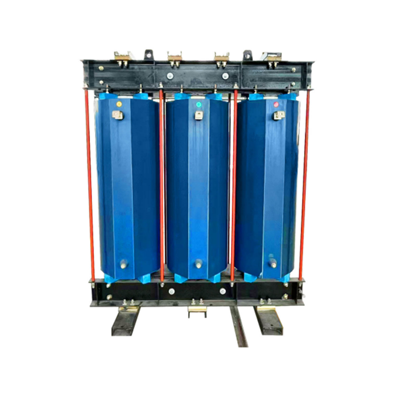 CKSC Dry-Type Iron Core Series ReactorsFor capacitor-bank protection and filtering duty, this resin-cast reactor offers multiple voltage and reactance ratings with low noise and maintenance-free operation.View Product →
Harmonics increase eddy-current losses and can create hot spots that are not visible on a simple nameplate rating. A transformer that performs well on a clean linear load may run hotter than expected when supplied by drives and rectifiers. For that reason, harmonic distortion mitigation should include the transformer specification, not only the filter package.
Ask for loss and temperature-rise data based on the actual non-linear load profile. Check whether derating is needed, confirm the neutral conductor arrangement, and consider future load growth. In indoor industrial and commercial projects, epoxy resin cast dry-type transformers are often chosen for their fire performance and low maintenance. Our 800-25000 kVA epoxy cast range is part of the distribution solution; the harmonic study still decides the final rating and impedance.
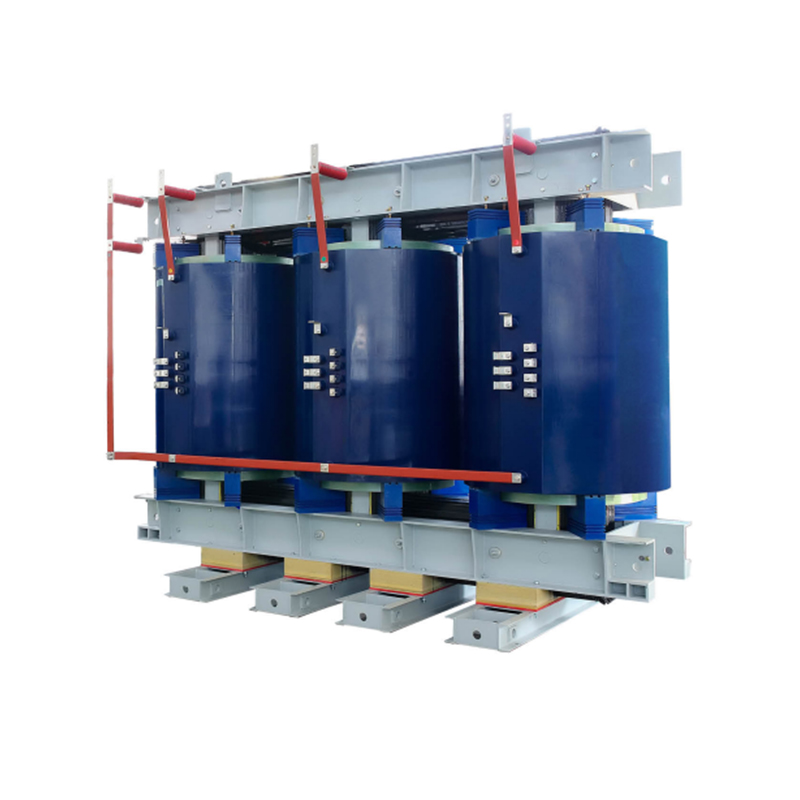 SC10 Epoxy Resin Cast Dry-Type TransformersFor indoor industrial and commercial distribution, this oil-free cast transformer range covers 800–25000 kVA with low partial discharge and flexible voltage configurations.View Product →
For outdoor or utility distribution, oil-immersed transformers remain common. The same rules apply: verify thermal margin, neutral current, and the effect of the expected harmonic spectrum. A standard low-loss distribution transformer can be a good choice, but it should not be expected to cancel harmonics by itself.
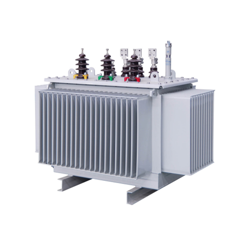 Fully Sealed S11/S13/S20/S22 Distribution TransformersFor dusty industrial and utility distribution, these fully sealed oil-immersed transformers cover 30–2500 kVA with corrugated tanks and optional monitoring devices.View Product →
Industrial plants often have the most complex mix: welding equipment, large drives, induction heating, and legacy power factor correction on the same bus. In industrial manufacturing, the first priority is usually to separate sensitive loads from distorting loads and to prevent resonance between capacitors and the supply.
Commercial buildings and infrastructure projects tend to have many small electronic loads rather than a single large rectifier. The harmonics may be lower in magnitude but widely distributed. In these cases, neutral sizing, transformer derating, and local filtering at large variable-speed drives matter more than a central passive filter.
Renewable and utility connections bring their own profile. Solar inverters and battery converters can inject harmonics, and the grid impedance at the connection point affects how those harmonics spread. A harmonic study should be part of the interconnection design, with filtering and transformer specifications coordinated rather than added later.
Harmonic distortion mitigation works best when it is treated as part of the electrical design, not as a rescue package after equipment starts failing. Measure first, reduce distortion at the source where you can, select filters and reactors for the actual spectrum, and specify transformers for the thermal duty they will see. That approach keeps the system stable, protects equipment, and avoids spending money on hardware that does not address the real problem.
If you are planning a new distribution system or correcting an existing one, our engineering team can review the load profile and help match transformers, reactors, and switchgear to the study results. The aim is not to sell the largest package, but to choose the smallest set of measures that delivers reliable power quality.
1.Types of High Voltage Switchgear The main categories of high voltage switchgear include Air-Insula...
View More1. Working Principle Oil-immersed transformers play a pivotal role in modern electrical power system...
View More1. Advantages of Distribution Dry Type Transformers Distribution dry type transformers have become i...
View More
 中文简体
中文简体 русский
 Español
 عربى
عربى