Get a Quote


A single voltage sag lasting 100 milliseconds can reset a PLC and halt an entire assembly line, costing an automotive plant $50,000 per minute in lost production. Power quality issues describe any deviation in voltage, current, or frequency that causes equipment to malfunction, trip, or degrade prematurely. In industrial facilities, these disturbances are not merely an inconvenience—they directly erode output, compromise safety, and inflate maintenance budgets.
Power quality is measured against a clean sinusoidal waveform at the nominal voltage and frequency. When the waveform distorts, dips, or swells, sensitive electronics react unpredictably. The root concern is not the existence of disturbance but its impact on process continuity. A well-designed power distribution system anticipates and contains these deviations before they reach critical loads.
Six primary categories of power quality issues dominate industrial environments:
Each type of disturbance leaves a distinct signature on equipment behavior. Recognizing the symptoms speeds up diagnosis and narrows the list of probable causes. Below is a consolidated view of what operators see, what causes it, and which assets suffer most.
| Issue Type | Typical Causes | Observable Symptoms | Most Affected Equipment |
|---|---|---|---|
| Voltage Sag | Large motor starting, utility faults, transformer energization | Lights dim momentarily, contactors drop out, VFDs trip on undervoltage | PLC, relays, motor drives, CNC machines |
| Voltage Swell | Load rejection, single-phase fault on a three-phase system, capacitor bank switching | Overvoltage alarms, premature lamp burnout, insulation stress | Power supplies, electronic ballasts, surge arresters |
| Transient | Lightning strikes, utility capacitor switching, arcing faults | Data corruption, immediate component failure, unexplained board damage | Computers, PLC I/O modules, networking gear |
| Harmonic Distortion | VFDs, UPS, rectifiers, arc furnaces, LED lighting | Overheated neutral conductors, transformer humming, erratic breaker tripping | Capacitors, transformers, motors, metering equipment |
| Voltage Unbalance | Unequal single-phase loads, blown capacitor fuses, asymmetrical faults | Motor vibrations, increased current in one phase, reduced motor life | Three-phase induction motors, VFD input rectifiers |
| Interruption | Utility recloser operations, equipment failure, accidental cable cuts | Complete loss of process, unscheduled downtime, data loss | All connected equipment |
Among these, harmonic distortion and voltage sags are the most pervasive in modern plants. The proliferation of non-linear loads has pushed harmonic currents to levels that were rare a decade ago. Meanwhile, sag remains the most frequent cause of nuisance tripping, often mistaken for equipment failure.
Disturbances originate either outside the facility gate or from equipment inside your own plant. External causes—lightning strikes, utility grid switching, or faults on adjacent feeders—are largely beyond your control. However, internal sources account for the majority of chronic power quality issues and are entirely manageable through design and maintenance choices.
Internally, the biggest offenders are the very devices that make modern automation possible. A VFD saves energy but injects harmonic currents back into the distribution network. Capacitor banks improve power factor but can create resonant conditions that amplify harmonics. Even routine operations like starting a large compressor can pull voltage down across an entire bus.
Common internal sources grouped by equipment type:
External causes, though less frequent, can be catastrophic. A single lightning strike near an overhead line induces transients of several thousand volts, overwhelming insulation systems not designed for such impulses. Utility capacitor bank switching, typically occurring early morning, generates oscillatory transients that propagate through the distribution network and into your facility.
Randomly swapping components or adding filters without data is expensive and often ineffective. A structured diagnostic approach, built around measurement and standard comparison, isolates the true source and quantifies severity. Three sequential steps form a reliable diagnosis pathway.
Step 1: Continuous monitoring with a power quality analyzer. Install a Class A power quality meter at the point of common coupling (PCC) and on major feeder breakers. A minimum monitoring period of 7 days captures both workday load patterns and off-peak baseline readings. Pay particular attention to voltage total harmonic distortion (THD-v) and current THD-i trends, as well as sag and swell event counts. Many facilities discover that harmonic levels peak during the third shift when a specific batch process runs.
Step 2: Compare against IEEE 519 or GB/T 14549 limits. IEEE 519 recommends voltage THD below 5% for systems below 69kV, with individual harmonic limits of 3%. For current distortion, limits are set based on the ratio of short-circuit current to load current (Isc/IL). If measurements exceed these thresholds, you have a quantifiable problem. For example, a 7.5% voltage THD at a 480V busbar demands immediate attention because transformer losses increase by 10–15% under such conditions.
Step 3: Locate the dominant harmonic source. Use the analyzer’s harmonic power direction function or temporarily switch off suspect loads one by one while observing THD changes. Harmonic current flows toward the source with the lowest impedance—usually the transformer feeding the bus. By measuring harmonic power flow at each branch circuit, you can pinpoint which feeder is injecting distortion. If disconnecting a specific VFD group drops the THD-v from 6% to 1.8%, that group is the primary contributor.
Once you know the type and magnitude of the problem, mitigation can be matched to the disturbance with precision. The table below maps common power quality issues to the most appropriate technologies, considering both effectiveness and cost.
| Technology | Targets | Typical Capacity | Cost Level | Key Limitation |
|---|---|---|---|---|
| Line Reactors (3% or 5% impedance) | Harmonic reduction, transient protection for VFDs | Matched to drive HP | Low | Limited harmonic reduction beyond 35% THD-i; no voltage regulation |
| Passive Harmonic Filters | Specific harmonic orders (5th, 7th, 11th) | Up to several Mvar | Medium | Fixed compensation; risk of resonance if system impedance changes |
| Active Harmonic Filters (APF) | Broad spectrum harmonic cancellation, power factor correction | 50 A to 3000 A modules | High | Higher initial investment; requires careful CT placement |
| Dynamic Voltage Restorer (DVR) | Voltage sag compensation | Up to 10 MVA | High | Limited energy storage; only sag correction |
| Static VAR Generator (SVG) | Voltage regulation, flicker reduction, power factor | Wide range, containerized options | High | Does not address harmonic current distortion directly without APF module |
| Uninterruptible Power Supply (UPS) | Complete power conditioning, sag, swell, interruption | KVA up to large industrial units | Highest per unit | Ongoing battery maintenance; efficiency losses |
For most VFD-centric installations, the first and most cost-effective line of defense is a 5% impedance line reactor mounted at the drive input. It brings THD-i down to approximately 25–35% at full load, compared to 50–100% without a reactor. If additional harmonic reduction is required—for instance, to meet IEEE 519 at the PCC—a passive filter tuned to the 5th harmonic can be added. Where multiple harmonic orders or dynamic load conditions exist, an active filter becomes the right tool.
Voltage sags demand a different approach. For individual critical loads, a constant-voltage transformer or a small online UPS may suffice. For entire production lines where process interruptions are unacceptable, a DVR or an industrial UPS with flywheel or battery storage is the only reliable answer. The decision hinges on the cost of downtime: if one sag event costs more than the DVR installation, the payback is immediate.
Proper equipment selection at the design stage eliminates entire categories of power quality issues before the first cable is terminated. Two asset classes—transformers and medium-voltage switchgear—play an outsized role in system immunity.
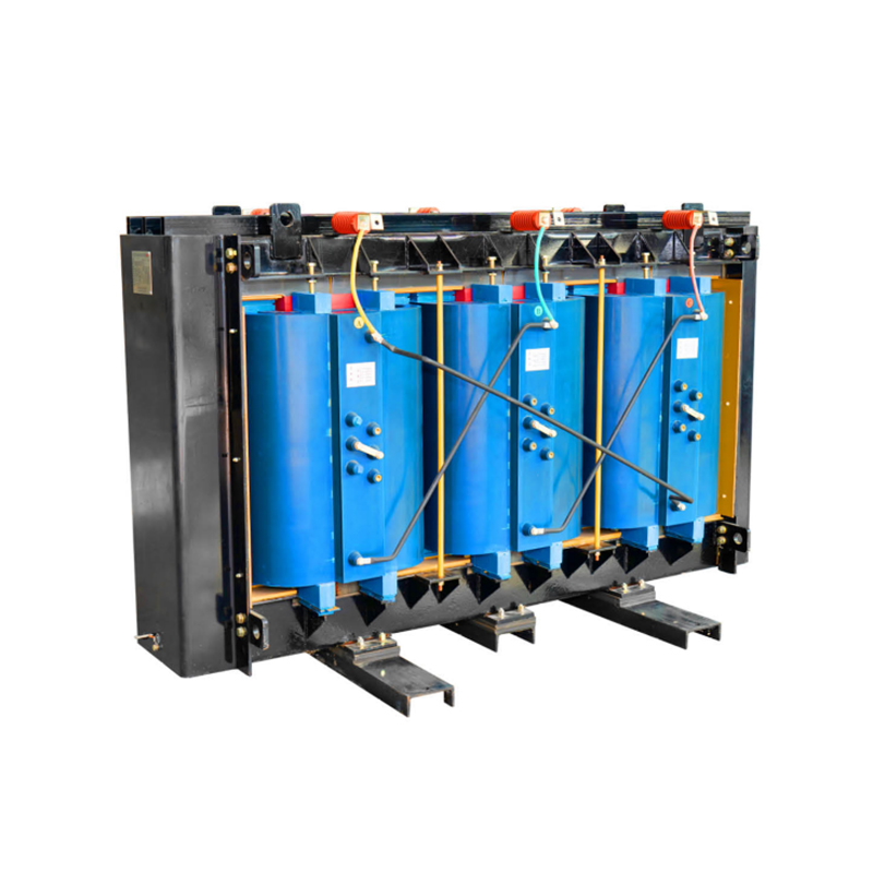
Transformers in harmonic-rich environments must handle additional losses without exceeding insulation temperature limits. Dry-type transformers, particularly those with epoxy resin encapsulation, tolerate harmonic current better than oil-immersed units because the solid insulation system resists thermal aging caused by localized hot spots. However, any transformer feeding non-linear loads must be derated per IEEE C57.110. A K-factor rating of K-13 or K-20 is common for industrial networks. When comparing choices for a harmonic-heavy 1500 kVA application, a dry-type unit with forced-air cooling often delivers superior lifecycle cost despite a slightly higher upfront price.
| Parameter | Dry-Type (Epoxy Cast) | Oil-Immersed |
|---|---|---|
| Harmonic tolerance | Excellent – solid insulation resists partial discharge under distortion | Moderate – extra eddy current losses in windings and tank |
| Thermal time constant | Longer – slower hot-spot buildup | Shorter – oil circulates heat quickly but hotspots can form |
| K-factor applicability | Commonly K-4, K-13, K-20 available | K-factor ratings less frequently applied; derating per C57.110 |
| Maintenance in harmonic duty | Low – no oil to test for dissolved gases | Requires periodic DGA to detect early winding degradation |
| Relative first cost | Higher for same kVA | Lower |
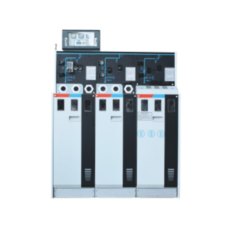
Switchgear insulation technology determines how well the assembly withstands transient overvoltages and partial discharge caused by distorted waveforms. Solid-insulated ring main units remove SF6 and replace it with epoxy-encapsulated busbars and breakers, achieving high impulse withstand levels with minimal maintenance. When combined with series reactors on incoming feeders, the switchgear forms a barrier that absorbs transients before they propagate downstream.
Specify a short-circuit current rating that includes harmonic contribution. A bus designed for 25 kA symmetrical might see actual peak currents 10–20% higher when harmonic currents add to the fundamental fault current. Adding a 6% or 7% detuning reactor ahead of capacitor banks avoids resonance near the 5th harmonic, a common pitfall in industrial plants where VFD penetration exceeds 40% of total load.
A 20 MW photovoltaic plant in a desert region began experiencing recurring inverter trips and voltage distortion exceeding 8% THD at the 35 kV point of interconnection. The utility issued a compliance warning, threatening curtailment. On-site measurements revealed that the central inverters were generating significant 5th and 7th harmonic currents, which resonated with the plant’s step-up transformer and cable capacitance, pushing the voltage distortion well beyond the grid code limit of 3%.
The engineering team deployed a two-pronged correction. First, they installed a 3 Mvar active harmonic filter at the main 35 kV bus, programmed to cancel the 5th and 7th harmonic orders dynamically as inverter output changed throughout the day. Second, they adjusted the on-load tap changer of the main power transformer to raise the secondary voltage by 2.5%, improving the inverters’ operating point and reducing their inherent harmonic production under light loading conditions. No inverter hardware modifications were required.
After commissioning, the voltage THD at the point of interconnection dropped from 8% to 2.1%, comfortably below the 3% limit. Inverter trips ceased, and annual production increased by approximately 1.2% due to eliminated curtailment hours. The total project cost—including the APF, CTs, engineering, and commissioning—achieved full payback in 14 months through increased energy sales alone.
Power quality issues are not random acts of nature; they are predictable consequences of how equipment interacts with the electrical network. Voltage sags, harmonics, transients, and unbalance each follow clear cause-effect chains that a structured diagnostic approach can quickly map. The mitigation options range from simple line reactors costing a few hundred dollars to plant-wide active filtering systems, and the right choice always begins with measurement, not assumption.
Facilities that treat power quality as a design parameter—not an afterthought—achieve higher uptime and longer asset life. Evaluate your medium-voltage transformer specification, switchgear insulation, and VFD installation practices against the benchmarks discussed here. A small investment in an impedance-grounded wye transformer or a detuned capacitor bank can prevent a seven-figure outage.
To develop a power quality audit tailored to your specific bus configuration, consult a specialist who can match monitoring equipment to your voltage level and load profile. The fastest path to cleaner power is a data-driven one.
1.Types of High Voltage Switchgear The main categories of high voltage switchgear include Air-Insula...
View More1. Working Principle Oil-immersed transformers play a pivotal role in modern electrical power system...
View More1. Advantages of Distribution Dry Type Transformers Distribution dry type transformers have become i...
View More
 中文简体
中文简体 русский
 Español
 عربى
عربى