
Get a Quote


Data centers are often described in terms of racks, cooling, and connectivity, but the foundation is a carefully engineered electrical path. Every server, storage array, and network switch depends on power that has been transformed, switched, protected, measured, and distributed many times before it reaches the rack. When teams ask us about IT and power distribution for data centers, the conversation usually starts with a simple question: where does the power come from, and what happens along the way? This guide walks through that path in practical terms, from the medium-voltage connection to the rack PDU.
At a high level, a data center electrical system has two jobs: deliver clean, continuous power to IT equipment and remove the heat that equipment produces. The table below gives a simplified view of the journey from the utility to the IT load.
| Stage | Typical equipment | Primary purpose |
|---|---|---|
| Utility connection | Medium-voltage feeders, metering, protection | Bring power into the site at the agreed voltage and capacity. |
| Medium-voltage distribution | MV switchgear, ring main units, breakers | Switch, protect, and divide power between transformers and feeds. |
| Transformation | MV/LV transformers | Step voltage down to the low-voltage distribution level. |
| Low-voltage distribution | LV switchgear, ATS, main-tie-main boards | Distribute power, transfer between sources, and coordinate protection. |
| Backup and conditioning | UPS, battery systems, static transfer switches | Ride through outages and improve power quality for IT loads. |
| Floor and rack distribution | PDUs, busway, remote power panels, rack PDUs | Deliver power to rows, racks, and individual devices. |
Not every facility uses every stage in the same way. A large colocation campus may have a dedicated utility substation, multiple MV feeds, and extensive LV distribution. An edge site or a small enterprise data room may use a prefabricated substation, a compact UPS, and simple rack PDUs. The principles remain similar: keep the path visible, avoid single points of failure, and make each stage easy to monitor and maintain.
Medium voltage is where the site connects to the utility and where the first major design decisions are made. MV switchgear provides switching, isolation, protection, and metering. In data centers, it is common to see dual feeds, main-tie-main arrangements, and protective relays coordinated with the utility and the downstream transformers. Ring main units are often used in distribution networks and prefabricated substations because they allow flexible feeding and isolation without a large switchgear room.
The transformer is the quiet workhorse of the data center power path. It steps medium voltage down to the low-voltage level used by UPS systems, PDUs, and mechanical equipment. The choice between dry-type and oil-immersed transformers usually comes down to location, fire safety, maintenance, and footprint. Dry-type transformers are common indoors because they avoid flammable liquid and simplify fire protection. Epoxy resin cast dry-type transformers are particularly familiar in electrical rooms where cleanliness and reduced maintenance are priorities. Oil-immersed transformers remain a strong option for outdoor yards and larger power blocks where their efficiency and thermal behavior are well understood.
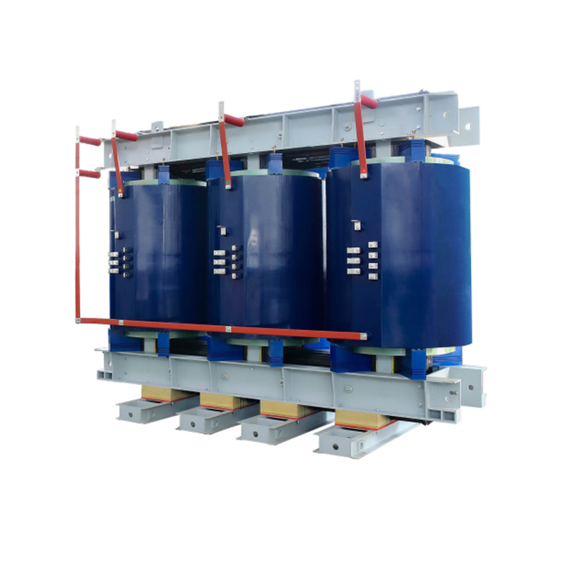 Epoxy Resin Cast Dry-Type Transformer for Indoor Power DistributionOil-free, fire-resistant transformer with vacuum pressure resin casting, suited to stepping medium voltage down for UPS systems, PDUs, and mechanical equipment.View Product →
Transformer selection should also consider harmonic content. Server power supplies, UPS rectifiers, and variable-speed drives can produce non-linear currents. If the harmonic profile is significant, the transformer may need a K-factor rating, additional derating, or a design that handles higher eddy-current losses. Efficiency matters as well, because transformer losses run continuously. A unit with low no-load and load losses can reduce operating cost over its life, but the right balance depends on the loading profile and the local energy tariff.
On the MV switching side, the equipment should match the site voltage, fault level, and operating philosophy. For 24 kV distribution, armored removable metal-enclosed switchgear is a practical format because it provides clear isolation and familiar safety interlocking. The exact relay settings, current transformer ratios, and arc-flash mitigation measures should be coordinated with the overall protection study.
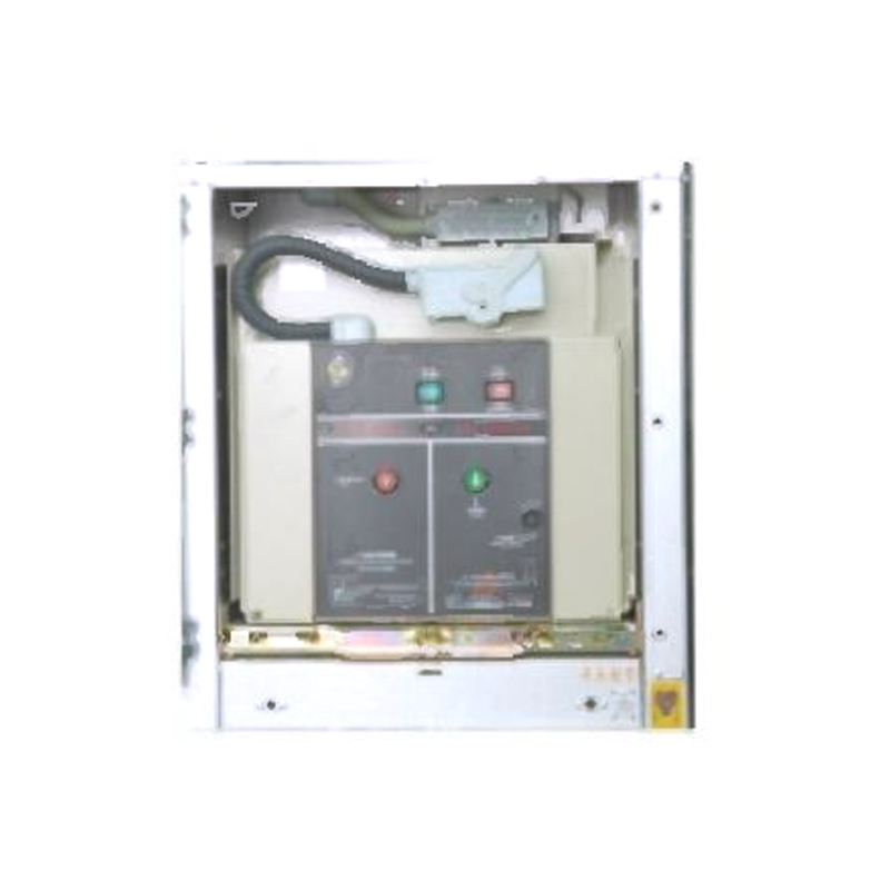 24kV Armored Removable Metal-Enclosed Switchgear for MV DistributionIndoor 24kV switchgear with mechanical five-prevention interlocks and vacuum circuit breakers, suited to receiving and distributing power at the site voltage and fault level.View Product →
Once power leaves the transformer, the low-voltage distribution system takes over. LV switchgear divides power into UPS input, mechanical loads, and other building services. Automatic transfer switches or main-tie-main schemes allow power to be sourced from different transformers or utility feeds. The goal is not simply to have two sources, but to have a switching and protection arrangement that can be tested and maintained without taking down the IT load.
UPS systems condition power and provide ride-through for short outages and generator start delays. In a typical data center, the UPS output feeds power distribution units, remote power panels, or busway systems. Busway offers flexibility in high-density halls because taps can be added or moved as rack layouts change. At the rack level, rack PDUs provide the final connection and often include metering, remote monitoring, and outlet-level control. This is where the IT and facilities worlds meet, and where clear labeling and accurate capacity data save time during installation and change management.
Redundancy is usually described in terms of N+1, 2N, or A+B power paths. The right choice depends on the criticality of the load, the available space, and the operating budget. A+B rack architecture, with dual-corded servers connected to separate power paths, is common in colocation and enterprise facilities. It is equally important to consider the mechanical load. Cooling units, pumps, and fans can consume a large share of the site power, and their electrical design affects the overall power usage effectiveness of the facility.
Data center electrical designs are judged on availability and efficiency, and those two goals can pull in different directions. More redundancy usually means more equipment, more losses, and more capital cost. A practical design makes the redundancy level explicit, then optimizes the rest of the system around it. Modular UPS systems, scalable busway, and spare transformer capacity can reduce the risk of overbuilding while keeping room for growth.
Power quality deserves early attention. Harmonic distortion can cause transformer heating, neutral overload, and nuisance tripping. Dry-type iron-core reactors are often used in capacitor banks and filter circuits to limit inrush and protect against harmonic resonance. In facilities with high concentrations of non-linear loads, a harmonic study is a better investment than a late-stage fix. The same is true for grounding and bonding. A clean grounding system supports reliable operation of sensitive IT equipment and helps protect people during maintenance.
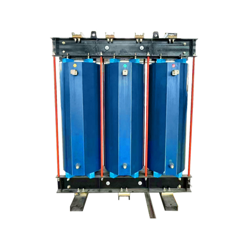 CKSC Dry-Type Iron Core Reactor for Current LimitingResin-cast, oil-free reactor for current limiting and compensation in capacitor banks and filter circuits, with low noise and maintenance-free operation.View Product →
Monitoring and metering should be designed as part of the power path, not added afterward. Metering at the utility connection, MV feeders, transformer secondaries, UPS outputs, and rack PDUs gives operations teams the data they need to track capacity, losses, and efficiency. When this data is organized around the same one-line diagram used by the design team, troubleshooting becomes much faster. More detailed power distribution solutions can be adapted to the project voltage, topology, and space constraints.
Commissioning is the final test of the design. Protection relays should be checked against the coordination study, transformers should be tested and inspected, and the transfer sequence between sources should be proven under realistic conditions. Thermal imaging after load is applied can reveal loose connections before they become failures.
From our experience as a transformer and switchgear manufacturer, the most successful projects are the ones where the electrical and IT teams compare assumptions early. A few practical checks help:
It also helps to involve the equipment supplier while the single-line diagram is still flexible. Small changes to transformer impedance, switchgear configuration, or busway routing can make a large difference in cable length, fault level, and future maintainability. If you are working through these choices, our frequently asked selection questions cover many of the details that come up in early project discussions.
IT and power distribution for data centers is not a single product decision. It is a chain of equipment and operating practices that must work together. The utility connection, MV switchgear, transformer, LV distribution, UPS, PDU, and rack PDU all play a role in keeping servers online. The best designs keep that chain visible, test it under realistic conditions, and leave enough flexibility for the next generation of IT equipment.
Whether you are planning a new facility or expanding an existing hall, the most useful starting point is a clear one-line diagram and an honest discussion about redundancy, efficiency, and growth. That is where good power distribution begins, and it is where the right equipment choices become much easier to make.
1.Types of High Voltage Switchgear The main categories of high voltage switchgear include Air-Insula...
View More1. Working Principle Oil-immersed transformers play a pivotal role in modern electrical power system...
View More1. Advantages of Distribution Dry Type Transformers Distribution dry type transformers have become i...
View More
 中文简体
 русский
 Español
 عربى
