
Get a Quote


Stand in front of a 33 kV switchgear panel, and the voltage display tells you the busbar is at 33,000 V. The meter never touches that busbar. A compact device mounted behind the panel steps the voltage down to 110 V or 100 V, and only that safe, proportional value reaches the instrument. That device is a potential transformer, and it is the reason high-voltage systems can be measured, protected, and controlled without exposing instruments or personnel to line voltage.
A potential transformer (PT), also known as a voltage transformer (VT), is an instrument transformer that reduces a high primary voltage to a standardized, much lower secondary voltage. Its secondary winding feeds measuring instruments, protective relays, synchronizing devices, and control circuits; it is not designed to deliver power.
The distinction matters more than the name. A power transformer transfers large amounts of energy, while a PT reproduces voltage faithfully. A typical PT handles only a burden of 10 VA to 75 VA, yet it must hold ratio error and phase error inside strict limits so that revenue metering, protection coordination, and switching decisions are based on an accurate picture of the network.
A PT operates on the same electromagnetic induction principle as any transformer. Its primary winding is connected in parallel across the line whose voltage must be measured. The alternating flux in the core induces a proportional voltage in the secondary winding. With a turns ratio of 100 to 1, an 11,000 V primary produces 110 V at the secondary at rated voltage. Three design points separate a PT from an ordinary power transformer:
A PT is compact compared with a distribution transformer, but its construction is demanding. The insulation must withstand full line voltage while the magnetic circuit maintains a precisely accurate ratio.
The core is built from high-permeability grain-oriented silicon steel laminations and runs at deliberately low flux density to reduce saturation and waveform distortion. The primary winding is designed for the full insulation level of the system and often includes tappings for ratio adjustment. The secondary winding is placed close to the primary to keep leakage reactance low, which directly improves phase accuracy.
For medium-voltage networks up to 35 kV, PTs are usually cast in epoxy resin or built with oil-paper insulation. Epoxy-cast PTs are common indoors and inside switchgear because they resist moisture and require little maintenance. Outdoor high-voltage installations more often use oil-immersed or gas-insulated designs.
Porcelain or silicone-rubber bushings bring the primary terminals out to the line connection, while the secondary terminals sit in a low-voltage terminal box. The enclosure rating and creepage distance must suit the installation site, whether that is indoor switchgear, an outdoor substation, or a coastal area with high pollution levels.
In a substation, almost every protection and metering function depends on the voltage image that the PT supplies. Its main applications are:
The choice of secondary connection, whether wye, delta, or broken delta, is a protection-engineering decision, and the same winding logic appears across the rest of the network. A useful starting point is the three-phase transformer connection guide, which explains how these configurations behave in practice.
Because relays and meters are built for standardized inputs, PTs are produced with well-defined secondary voltage levels, as shown in Table 1.
| Connection method | Typical rated secondary voltage | Application |
|---|---|---|
| Phase-to-phase | 100 V, 110 V, or 120 V | Line-voltage measurement, revenue metering, synchronizing |
| Phase-to-neutral | 57.7 V or 63.5 V | Phase-voltage measurement, relay voltage inputs |
| Broken-delta residual winding | 33.3 V or 36.7 V | Zero-sequence voltage detection for ground-fault protection |
The PT is often mentioned together with the current transformer (CT) because both are instrument transformers: the PT measures voltage, while the CT measures current. They cannot be swapped, and connecting either one incorrectly creates a serious hazard.
| Feature | Potential transformer (PT) | Current transformer (CT) |
|---|---|---|
| Quantity measured | Voltage | Current |
| Primary connection | In parallel with the line | In series with the line |
| Secondary output | Proportional voltage, for example 100 V or 110 V | Proportional current, for example 5 A or 1 A |
| Secondary operating rule | Never short-circuit the secondary | Never open-circuit the secondary |
| Core operating point | Low flux density, designed for linearity | Moves toward saturation under fault current |
| Typical accuracy classes | 0.2 / 0.5 / 1 for metering; 3P / 6P for protection | 0.2S / 0.5S for metering; 5P / 10P for protection |
| Primary role | Voltage measurement, protection, synchronism, residual voltage detection | Current measurement, overcurrent and differential protection, metering |
The operating rule to remember: a PT behaves like a small voltage source, so its secondary must never be short-circuited; a CT behaves like a current source, so its secondary must never be open-circuited. Both secondary circuits must always be grounded to keep personnel and equipment safe.
The value of a PT is only as good as its accuracy under real service conditions. Two parameters dominate the specification: accuracy class and burden.
Standards such as IEC 61869-3 define metering classes (0.2, 0.5, 1.0, 3.0) and protection classes (3P, 6P). A class 0.5 metering PT, for example, limits voltage error to 0.5 percent at rated burden, while protection classes allow wider error but must keep reliable performance during transient overvoltage.
Burden is the load connected to the secondary, expressed in volt-amperes (VA). A relay, a meter, and the interconnecting wiring may together present 25 VA, so the PT must have a rated burden at least equal to that value. If the connected burden rises beyond the rated burden, ratio error and phase error grow beyond the class limit.
A PT never replaces a power transformer. On a 10 kV or 20 kV distribution feeder, one or more PTs supply revenue meters, protection relays, and remote terminal units, but the actual power transfer depends on a separate distribution transformer. Mixing up the two roles is one of the most common specification mistakes.
For utilities and industrial users, the workhorse of power distribution remains the oil-immersed transformer. Low-loss 10 kV and 20 kV oil-immersed distribution transformers in the S11-S22 series are routinely paired with PT-based metering panels in substations and distribution rooms. The boundary between the two duties is covered in the practical guide on power transformer vs distribution transformer selection.
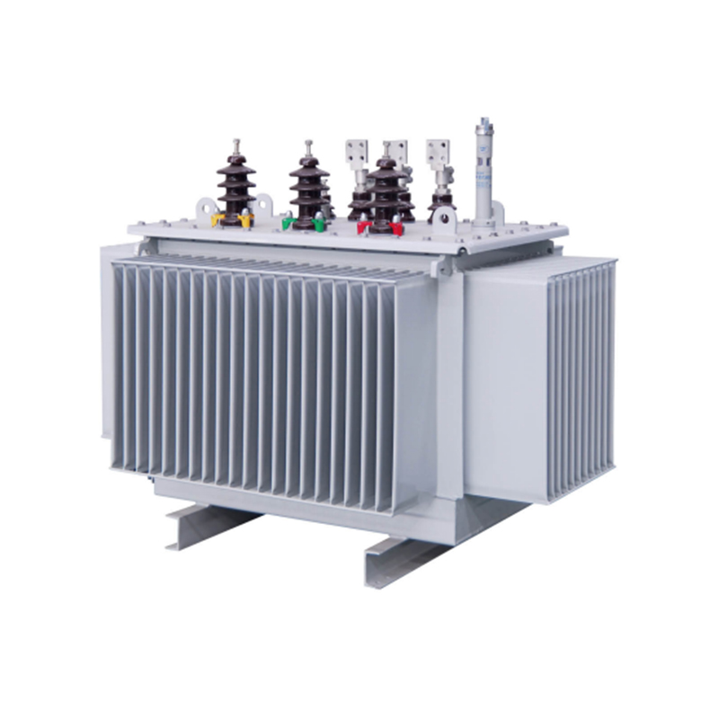 Custom 10KV、20KV S11/S13/S20/S22 Oil-immersed distribution transformer SuppliersDetong Transformer China wholesale 10KV、20KV S11/S13/S20/S22 Oil-immersed distribution transformer suppliers and 10KV、20KV S11/S13/S20/S2...View Product →
When the transformer must be mounted inside a building, hospital, mall, or industrial workshop, dry-type construction avoids the fire and leakage risks of oil-filled equipment. Many projects choose epoxy resin cast dry-type transformers from 800 kVA up to 25,000 kVA because the cast resin windings withstand humidity, dust, and partial discharge over long service intervals.
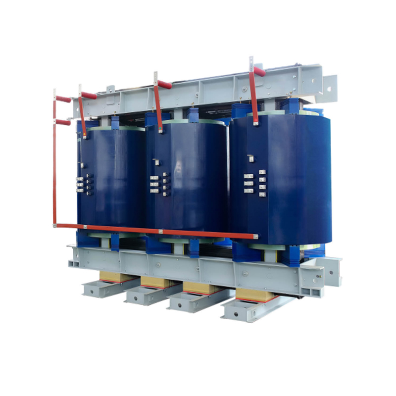 Custom Epoxy Resin Cast Dry Type Transformer - 800 to 25000 kVA Suppliers, CompaDetong Transformer China wholesale Epoxy Resin Cast Dry Type Transformer - 800 to 25000 kVA suppliers and Epoxy Resin Cast Dry Type Trans...View Product →
In tight distribution points, the PT, metering cubicle, switchgear, and transformer can share one housing. For feeder pillars, rural networks, and commercial enclosures, an American box-type combined transformer puts incoming protection, metering, and the distribution transformer in a single weatherproof cabinet, shortening installation time and simplifying maintenance. If you are reviewing the whole assembly around the PT, the comprehensive guide to high-voltage switchgear explains how voltage transformers, breakers, and bushings work together in the same panel.
 Custom American Box-Type Combined Transformer Suppliers, Company - Zhejiang DetoDetong Transformer China wholesale American Box-Type Combined Transformer suppliers and American Box-Type Combined Transformer company, d...View Product →
A potential transformer is a small but essential link between the high-voltage network and the low-voltage instruments that supervise it. It steps voltage down safely, holds the ratio and phase within tight limits, and provides the isolation that protects people and control gear.
When you specify a PT, check the ratio, accuracy class, burden, insulation level, and secondary connection; select a unit rated for the system maximum voltage and earthing arrangement; and respect the secondary circuit rules, never short-circuit a PT secondary, never open-circuit a CT secondary, and always ground the secondary side. And if the project actually needs the transformer that carries the load, remember that a PT is the eyes of the protection system, not a replacement for the power transformer itself.
1.Types of High Voltage Switchgear The main categories of high voltage switchgear include Air-Insula...
View More1. Working Principle Oil-immersed transformers play a pivotal role in modern electrical power system...
View More1. Advantages of Distribution Dry Type Transformers Distribution dry type transformers have become i...
View More
 中文简体
中文简体 русский
 Español
 عربى
عربى