
Get a Quote


Stand outside the fence of a medium or high voltage substation and you will see a collection of steel, porcelain and copper that looks complicated at first glance. Spend a few minutes learning what each item is for, however, and the whole installation begins to read like a diagram. In our work supplying transformers, reactors and switchgear to utilities, industrial plants, transport projects and renewable energy sites, we have watched experienced engineers walk a new site for the first time and name every component within minutes, simply because they understood the function behind each shape.
This article breaks the components of a substation down into logical layers, from the transformer that performs the voltage conversion to the small auxiliary systems that keep everything else alive. Whatever your role, whether design, procurement, operations or maintenance, the goal is the same: understand what each part does, and you will understand why it is specified the way it is.
Before listing hardware, it helps to list duties. A substation is a node where several functions are deliberately concentrated in one place:
Every component discussed below exists to serve one or more of these duties. That is the simplest way to judge whether a piece of equipment belongs in a particular design.
The power transformer is usually the largest and most expensive item on site. It converts energy from one voltage level to another through magnetic induction, and its rating sets the capacity limit for everything downstream. In transmission substations you will typically see large oil-immersed units, often with on-load tap changers for voltage regulation. In distribution substations, the transformers are smaller but far more numerous, stepping 10 kV, 20 kV or 35 kV down to the utilisation voltage used by factories, buildings and neighbourhoods.
The choice between oil-immersed and dry-type construction is one of the first decisions a designer faces. Oil-immersed transformers handle very large capacities efficiently and are the default outdoors. Dry-type transformers, particularly epoxy resin cast units, avoid flammable liquid, tolerate indoor installation well and suit buildings, tunnels, metro stations and other locations where fire risk and maintenance access are sensitive topics.
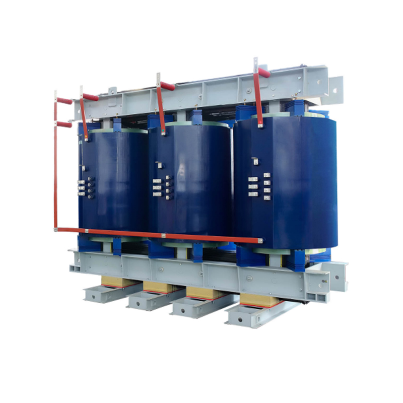 Epoxy Resin Cast Dry Type Transformer - 800 to 25000 kVAFor this SC10-800~2500 series epoxy resin cast dry type transformers, both high and low voltage windings utilize an advanced vacuum pressure resin casting process. Thi...View Product →
Whatever the cooling method, the transformer is the component that defines the substation's rating, impedance, noise level and loss profile, so its specification deserves the most attention during design review.
If the transformer changes the voltage, the switchgear decides where that power goes and when it stops. This layer includes circuit breakers, disconnecting switches, earthing switches and, in many distribution networks, ring main units. Together they allow operators to reconfigure the network, isolate faulty sections and restore supply to healthy circuits.
A circuit breaker is the only device in a substation designed to interrupt fault current. Vacuum breakers dominate medium voltage applications, while gas-insulated designs are common where space is tight or where the surrounding environment demands a sealed, compact arrangement. Selection usually hinges on rated voltage, short-circuit current, breaking capacity, operating mechanism and the required number of operations between maintenance intervals.
Disconnectors, also called isolators, cannot break load current, but they provide the visible isolation that makes safe maintenance possible. Earthing switches then connect the isolated section to the station earth so that accidental energisation cannot harm the people working on it. A well-designed interlocking scheme ties these devices, the circuit breaker and the earthing switch together so that the sequence cannot be performed incorrectly.
Because switchgear families vary widely in insulation medium, compartment design and automation level, it is worth studying a comprehensive guide to high voltage switchgear types and safety before freezing a specification.
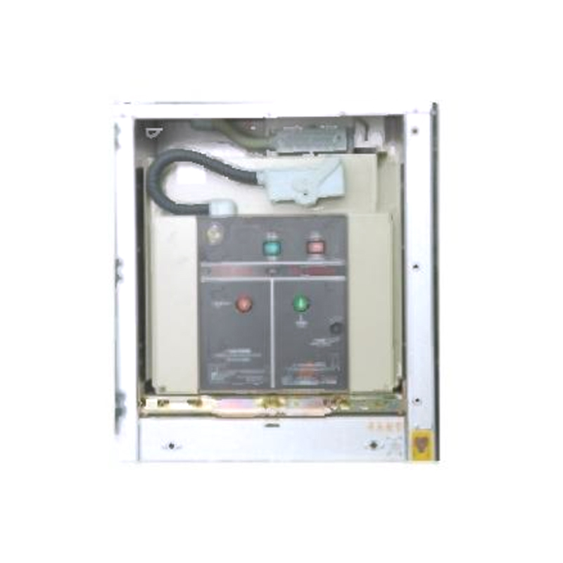 24kV Armored Removable Metal-Enclosed SwitchgearThis switchgear features an assembled structure, securely connected by high-strength bolts and rivet nuts. To ensure operational safety, the main switch, handcart, and...View Product →
These three groups are smaller than a transformer but no less important, and they are frequently the components that determine whether a protection scheme works as intended.
In coastal, mining, desert or heavily polluted locations, the specification of insulators and arresters deserves as much scrutiny as the main equipment, because creepage and sealing failures are among the most common causes of unplanned outages.
The busbar is the electrical hub of the substation. Whether it is rigid tubular aluminium, stranded conductor or a fully enclosed bus inside gas-insulated equipment, it collects incoming and outgoing circuits and distributes power between them. Conductor sizing considers continuous current, short-circuit withstand, mechanical loading from wind and ice, and the clearance distances required at the site's altitude and impulse level.
Alongside the conductors, many substations include reactive compensation. Capacitor banks raise voltage and reduce losses on heavily loaded feeders, while reactors serve two different purposes: shunt reactors absorb capacitive charging current on long lines, and series reactors limit fault current or protect capacitor banks from inrush and harmonic resonance. Where a capacitor bank is installed indoors or in a compact arrangement, a dry-type iron core reactor is often the practical choice because it avoids oil and simplifies maintenance.
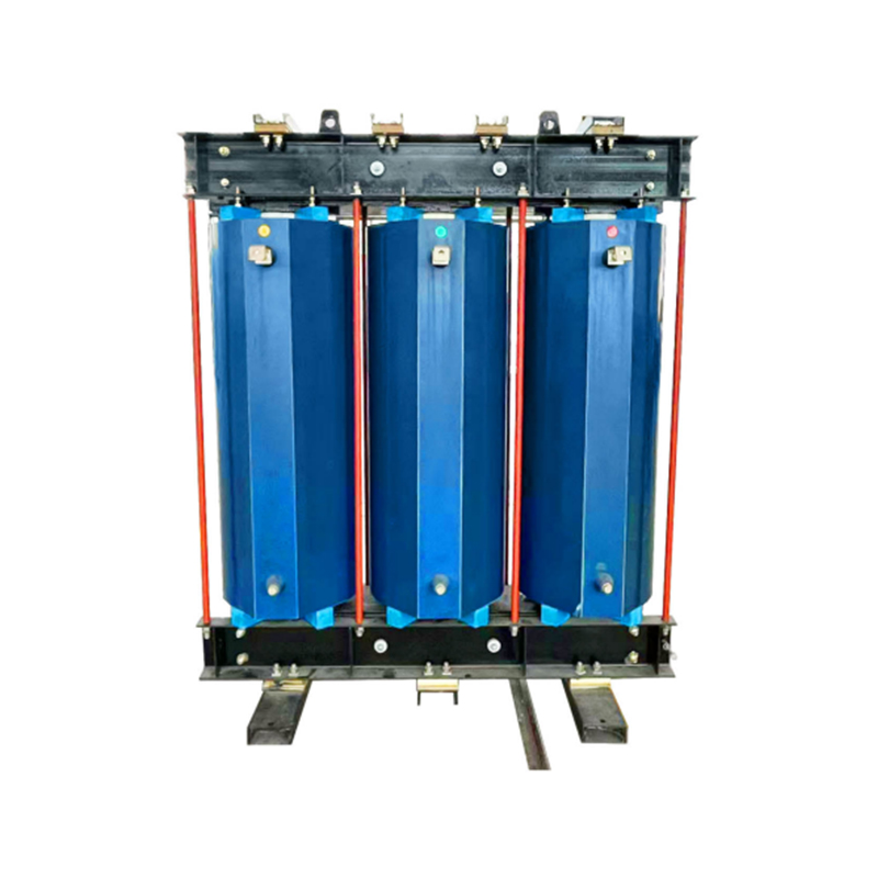 Dry-Type Iron Core Series ReactorThe iron core columns and windings of this reactor series are entirely resin-cast, which provides better electrical performance and mechanical strength. Through carefu...View Product →
Everything described so far is power equipment. What makes it a working substation is the secondary system that watches, decides and acts. Protection relays compare measured current and voltage against settings, and when a fault is detected they trip the relevant circuit breakers within milliseconds. Modern installations use numerical relays with communication ports, feeding a substation automation system that links to the control centre.
The auxiliary systems that support this layer are easy to overlook until they fail:
The table below summarises the main items and where they normally appear, which is useful when reviewing a single line diagram or preparing a bill of materials.
| Component | Primary Function | Usual Location |
|---|---|---|
| Power transformer | Voltage transformation | Outdoor bay or indoor cell |
| Circuit breaker | Fault and load current interruption | Switchgear room or outdoor bay |
| Disconnector | Visible isolation for maintenance | On both sides of breakers |
| Instrument transformer | Measurement and protection signals | Near breakers and transformers |
| Surge arrester | Overvoltage protection | Line entrance and transformer terminals |
| Busbar | Power collection and distribution | Central structure of the yard |
| Protection relay | Fault detection and tripping | Control and relay panels |
| DC battery system | Backup supply for protection and control | Control building |
Not every substation contains every component, and the mix shifts with the duty the station performs:
A component list is only the beginning. The details that decide whether a substation performs well for thirty years are the ones written into the specification: rated voltage and insulation level, short-circuit withstand, temperature rise limits, ingress protection, altitude and seismic requirements, and the pollution level of the surrounding environment. Maintenance access matters just as much, because a transformer that cannot be inspected or a switchgear panel that cannot be withdrawn is a liability rather than an asset.
It also pays to think about how the pieces are supplied. When transformers, reactors, switchgear and prefabricated substations come from one manufacturing source, ratings are easier to coordinate, interfaces are fewer, and responsibility during commissioning is clear. We build our range with exactly that logic in mind: epoxy resin cast and amorphous alloy dry-type transformers up to large capacities, oil-immersed power and distribution transformers, iron core reactors, ring main units, metal-enclosed switchgear and box-type substations, all serving power utilities, industry, transport, buildings, telecommunications, new energy and mining projects.
If you are preparing a substation design, comparing transformer options or checking whether an existing installation still matches its original intent, our engineering team is happy to review the component list with you and suggest a configuration that fits the site, the load profile and the maintenance resources you actually have.
1.Types of High Voltage Switchgear The main categories of high voltage switchgear include Air-Insula...
View More1. Working Principle Oil-immersed transformers play a pivotal role in modern electrical power system...
View More1. Advantages of Distribution Dry Type Transformers Distribution dry type transformers have become i...
View More
 中文简体
中文简体 русский
 Español
 عربى
عربى