
Get a Quote


A circuit breaker does only half of its job if nobody knows which position it is in. The primary contacts carry the load current and interrupt faults, but the signals that tell an operator, a PLC or a SCADA system what the breaker is actually doing come from a much smaller component: the circuit breaker auxiliary switch. It is one of the least expensive items inside a switchgear cubicle, and one of the most frequently mis-specified.
At Detong Transformer we manufacture dry-type and oil-immersed transformers, dry-type iron-core reactors, box-type substations and high-voltage switchgear for distribution networks. The auxiliary contacts inside our breakers and ring main units are the same ones our customers wire into their protection and control schemes every day. This guide explains what an auxiliary switch is, how it differs from the other contacts on a breaker, how to specify it, and how to keep it reliable over a long service life.
An auxiliary switch is a contact block that is mechanically driven by the main operating shaft of a circuit breaker. Because it is linked to the mechanism, it changes state every time the breaker opens or closes. Because it is electrically isolated from the primary circuit, it never carries load current and never has to interrupt a fault. Its work is limited to switching control-level signals, which is exactly why it is so useful.
The mechanical link is usually a cam, a crank or a push rod inside the mechanism housing. The contact block itself sits in a compartment of its own, separated from the live parts by the insulation distances required for the breaker's rated voltage, so the auxiliary circuit can be wired with ordinary control cable. Typical blocks are stackable, and a single breaker is often fitted with two, four or even eight contacts, arranged as normally open (a contacts) and normally closed (b contacts).
Engineers sometimes use the two terms interchangeably, but an auxiliary switch follows the breaker position in every case, whether the breaker was opened by a protection trip, by a remote command or by hand. A trip alarm contact, sometimes called a bell alarm contact, behaves quite differently: it operates and latches only when the breaker has tripped through its protection, which makes it the right choice for fault annunciation. Spring-charge contacts, rack-position switches and cell or door switches are separate devices again, each reporting one specific mechanical state rather than the main contact position.
Most auxiliary contacts on a medium-voltage breaker follow the patterns shown in the table below. The exact behaviour depends on the mechanism, so always confirm the arrangement against the manufacturer's wiring diagram before you terminate anything.
| Contact type | Behaviour | Typical function |
|---|---|---|
| Normally open (a contact) | Closes when the breaker closes | Breaker-closed indication, closing-circuit enable |
| Normally closed (b contact) | Opens when the breaker closes | Breaker-open indication, trip-circuit supervision |
| Changeover contact | Transfers from NC to NO with the mechanism | Interlocking, remote and local selection |
| Trip alarm (bell alarm) | Operates and latches only after a protection trip | Fault annunciation and lockout signalling |
Two conventions are worth remembering. In IEC documentation, "a" means a contact that closes with the breaker and "b" means a contact that opens with the breaker. On a stored-energy breaker, the contact reporting a charged closing spring is not an auxiliary switch at all, because it is driven by the charging mechanism rather than by the main shaft.
The component is small, but a feeder without a trustworthy set of status contacts is a feeder nobody can operate with confidence. Four duties come up again and again in our projects.
Panel lamps, mimic diagrams, PLC inputs and event logs all depend on a clean, isolated contact that mirrors the breaker. Without a normally closed contact to prove that the breaker is open, a maintenance team cannot safely plan work on a downstream cable.
Auxiliary contacts enforce the logic that keeps people out of trouble: they block a closing command when the breaker is already closed, prevent an earthing switch from being operated while the breaker is in service, and confirm that a busbar transfer sequence has reached the correct state. In automated and unmanned substations they feed the remote terminal unit, so every switching operation is reported to the control centre.
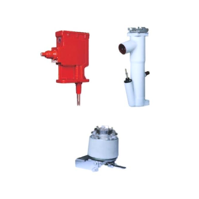 Solid Insulation Intelligent Ring Main UnitWithin the same power supply unit, the GTXGN-12 Solid Insulation Intelligent Ring Main Unit's three phases (A, B, and C) are each comprised of independent modules, off...View Product →
That reporting path is precisely what makes our intelligent ring main units useful in compact distribution networks, where a remote operator needs to see breaker and switch positions without visiting the site. Condition monitoring also depends on the same contacts: an operation counter built on an auxiliary contact tells you when the interrupting chamber or the mechanism is approaching the end of its expected life.
Most problems with auxiliary contacts come from the specification stage rather than from the product itself. Working through the following points takes only a few minutes and prevents years of nuisance alarms.
Order spare contacts with the breaker rather than later. Retrofitting a block into a live cubicle means an outage, a re-test and a new as-built drawing, which costs far more than the part itself.
Because we build transformers, reactors and switchgear under one roof, our customers often receive a complete package: the transformer, the medium-voltage switchgear and the outgoing feeders arrive with a coordinated control and indication scheme instead of three separate wiring philosophies.
In metal-clad switchgear with withdrawable breakers, auxiliary contacts travel with the truck, so position indication stays valid in both the test and service positions. This is the arrangement we use across our indoor metal-armored centrally mounted removable switchgear range, where the auxiliary block, the position switch and the trip alarm contact work together to give the operator a complete picture of each feeder.
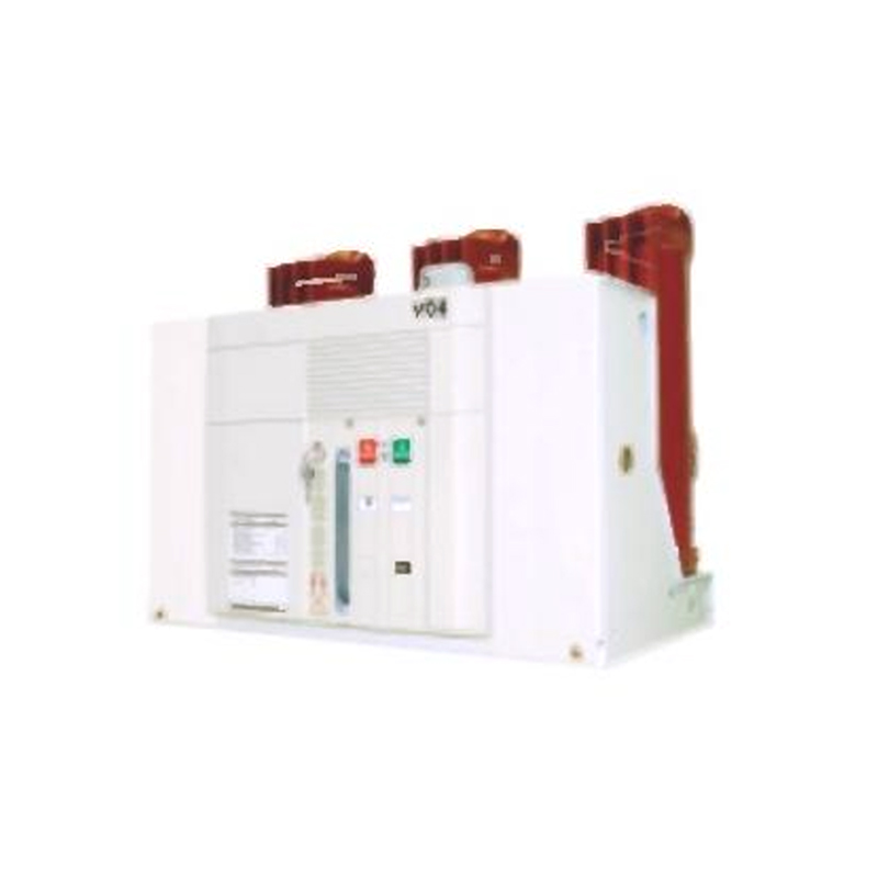 Indoor Metal-Armored Centrally Mounted Removable SwitchgearThis switchgear offers intelligent control capabilities, enabling the installation of various microcomputer-based integrated relay protection devices on the relay comp...View Product →
Ring main units follow a similar logic on a smaller footprint. Our AC metal-enclosed ring network switchgear uses auxiliary contacts for cable-fault indication logic, for interlocking between the ring switches and the tee-off circuit, and for status reporting to a distribution automation platform.
 AC Metal-Enclosed Ring Network SwitchgearThe switchgear achieves a compact volume, comparable to both vacuum and SF6 gas-insulated ring main units. Its design effectively resolves the practical challenges and...View Product →
Where the auxiliary circuits are wired back to a common protection and control panel, it pays to keep contact allocation consistent across every cubicle, so a technician opening any panel recognises the same terminal numbering and the same spare contacts.
Auxiliary contacts need almost no attention once they are installed correctly, but the commissioning checks are not optional. We recommend the following sequence.
During routine maintenance, check contact resistance, look for pitting or discoloration caused by arcing, and inspect the mechanical link for wear or lost motion. A contact that no longer changes state cleanly is a safety issue, not a cosmetic one. If you are also reviewing the breaker these contacts are mounted on, our companion article on vacuum circuit breaker selection and total cost of ownership covers the wider selection picture.
Most low-voltage and medium-voltage breakers provide at least one mounting position for an auxiliary contact block, but the kit has to be listed for that specific mechanism. Check the breaker's order code and accessory list before you commit.
Two is the absolute minimum, one normally open and one normally closed for indication. In practice, four to six contacts are common once you add trip-circuit supervision, interlocking, remote signalling and a spare pair.
Alternating current passes through zero twice per cycle, which helps the arc extinguish. Direct current has no such natural break, so the same contact that handles several amperes at 240 V AC may only be good for a fraction of an ampere at 220 V DC.
On withdrawable breakers it is often possible, but the cubicle must be de-energised, the mechanism re-tested and the drawings updated. Ordering the contacts with the original equipment is simpler and cheaper.
A circuit breaker auxiliary switch costs very little and carries no primary current, yet it determines whether a protection and control scheme can be trusted. Specify the right contact count, respect the DC ratings, test the behaviour on site, and the smallest component in the cubicle will quietly do its job for the life of the installation.
If you are planning a transformer and switchgear package and want the auxiliary circuits arranged around your own control philosophy, our engineering team is glad to help. Share your single-line diagram and control requirements, and we will come back with a configuration that fits.
1.Types of High Voltage Switchgear The main categories of high voltage switchgear include Air-Insula...
View More1. Working Principle Oil-immersed transformers play a pivotal role in modern electrical power system...
View More1. Advantages of Distribution Dry Type Transformers Distribution dry type transformers have become i...
View More
 中文简体
中文简体 русский
 Español
 عربى
عربى