
Get a Quote


When a 2500 kVA transformer's main breaker trips during start-up of a 400 kW motor, the usual response is to call for a bigger breaker. The breaker, however, may already be correctly rated. The cause is often a mismatch between the protection settings and the actual load current, transformer inrush, and downstream fault-clearing time.
Circuit breaker protection settings are not guesswork. They are a coordinated set of pickup values and delays that must match the thermal limits of the equipment, the magnitude of the fault current, and the need for selectivity in the network.
Modern molded case, air circuit, and medium-voltage breakers allow the user to adjust several trip parameters. In low-voltage breakers, these are typically called Ir, tr, Isd, tsd, Ii, and Ig. In medium-voltage switchgear, the same concepts appear as protective relay settings. The table below gives a practical summary of the primary adjustment ranges used in LV distribution breakers.
| Function | Pickup Range | Delay Range | What It Protects |
|---|---|---|---|
| Long-time | 0.4 to 1.0 x In | 0.5 to 15 s | Overloads and thermal limits |
| Short-time | 1.5 to 10 x Ir | 0.05 to 0.5 s | Selectivity for short circuits |
| Instantaneous | 6 to 15 x In | Not applicable | Severe short circuits |
| Ground fault | 0.2 to 0.7 x In | 0.1 to 0.8 s | Earth leakages and insulation damage |
Use these values only as a starting point. The actual limits depend on the breaker platform, the reference ambient temperature, and the installation environment. Always verify the selected settings against the equipment's time-current curve.
The long-time setting is the continuous overcurrent protection. Ir is the pickup point at which the breaker begins to time out, and tr is the duration before it trips. On many frames, Ir is adjustable from 0.4 to 1.0 times the rated current. You must set Ir above the maximum sustained load current, but below the conductor or equipment ampacity. For example, a 2500 kVA dry-type transformer on a 10 kV system draws about 144 A at full load. With a 200 A breaker frame, Ir may be set to 170 A to allow for temporary overload while still protecting the transformer from sustained thermal stress.
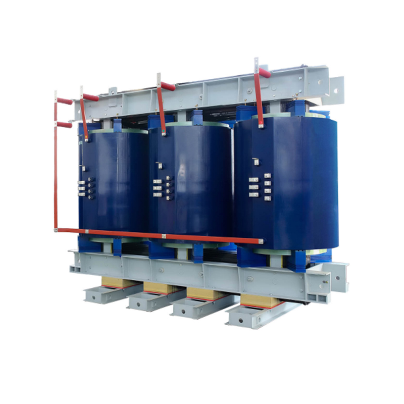 Epoxy Resin Cast Dry-Type Transformer for 800 to 2500 kVAThis transformer supports continuous overload protection with adjustable long-time settings, making it suitable for applications where sustained thermal stress and motor starting transients must be balanced.View Product →
The long-time delay, tr, controls how fast the breaker responds to a sustained overload. A high setting, such as 10 to 15 seconds, allows motor startups and transient peaks to pass, but it also leaves the conductor hot for longer. A lower setting, around 0.5 to 2 seconds, gives faster protection for cables and transformers with low thermal capacity.
Short-time protection provides delayed tripping for moderate short-circuit currents. Isd is normally adjustable from 1.5 to 10 times Ir, and tsd can be set from 0.05 to 0.5 seconds. This time delay lets a downstream breaker clear a fault before the upstream breaker trips. Without it, a branch fault could shut down the entire main bus. In industrial plants, a common cause of nuisance trips is an Isd set too low relative to motor starting currents.
When the available short-circuit current is very high, limiting it gives the protection system more responsive room. Series reactors are widely used in capacitor bank and distribution circuits to reduce current rise and make coordination easier.
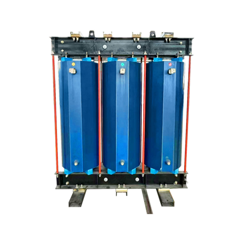 Dry-Type Iron Core Series Reactor for Current LimitingThis reactor reduces short-circuit current and improves protection coordination, offering maintenance-free operation with resin-cast windings and low noise for reliable use in distribution circuits.View Product →
Consider a 2000 A main breaker supplying three 800 A feeder breakers. If Isd on the main is set to 4 x Ir and tsd to 0.3 seconds, the feeders can clear a short circuit at their terminals before the main sees the fault. A zero-delay instantaneous setting on the main would defeat this selectivity.
The instantaneous trip clears bolted short circuits before the fault current causes devastating mechanical damage. On low-voltage breakers, Ii is typically adjustable between 6 and 15 times the frame rating, with no intentional delay. For transformer feeders, keeping Ii above the transformer inrush current is critical. Inrush can reach 10 to 12 times rated current for a few cycles, and an over-sensitive instantaneous setting would trip the breaker on every energization. In medium-voltage breakers, instantaneous protection is implemented in the relay, where it is often coordinated with the short-time curve by using a separate instantaneous pickup above the downstream fault level.
The instantaneous trip also reduces arc flash energy by clearing the fault in barely one cycle. In LV systems, a lower instantaneous setting shortens the incident energy, but only if it does not conflict with inrush. For transformers, many utility standards recommend that the instantaneous pickup be at least 1.5 times the calculated transformer inrush current.
Ground-fault protection operates differently from phase overcurrent. It detects fault current returning through the earth or an external path. The pickup Ig is often adjustable from 20% to 70% of the breaker rating, and the delay tg may be 0.1 to 0.8 seconds. If set too low, the breaker will nuisance-trip on harmless leakage currents from cable capacitance or equipment filters. If set too high, an insulation failure can cause burning and arc damage before the breaker reacts. Ground fault timers are often set in inverse-time mode to balance arc energy and sensitivity.
In a solidly grounded system, the neutral current path is well defined, and the ground fault pickup can be set lower. In a high-impedance grounded system, the fault current is limited, and ground fault protection must be set much more sensitive, sometimes below the phase overcurrent settings, because a low-value fault would otherwise never be seen.
In medium-voltage circuits, the breaker protection settings are usually entered through the protection relay inside switchgear. The setting philosophy is the same, but the values are scaled to the secondary current transformer ratio. A 24 kV armored removable switchgear unit with a vacuum circuit breaker is a typical location for this type of protection. Here, the long-time pickup addresses transformer overload, the short-time pickup coordinates with low-voltage main breakers, and the instantaneous pickup is set above the transformer inrush but below the maximum permissible through-fault current.
For a transformer feeder, the short-time pickup should be above the secondary short-circuit current divided by the transformer ratio, while remaining below the transformer's through-fault withstand limit. The instantaneous trip is often disabled or set above the inrush peak so it does not operate on switching. For a compact ring distribution network, a gas-insulated ring main unit may combine load-break switches and fused vacuum breakers, where the protection settings are fixed by the fuse curve rather than an adjustable trip unit. Before choosing between a fuse and a breaker, consider the difference in coordination behavior. The fuse versus circuit breaker discussion explains how clearing times and current-limitation differ.
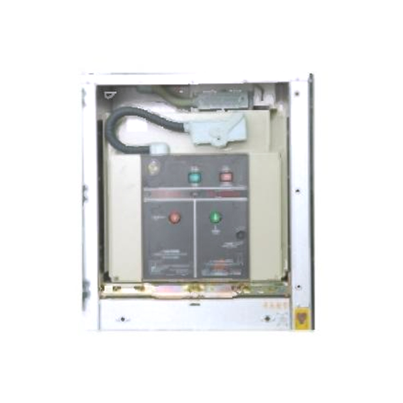 24kV Armored Removable Metal-Enclosed Switchgear with Vacuum BreakerThis switchgear provides reliable interruption and interlocking for ring networks, enabling coordination with fuse or breaker protection settings to ensure safe and selective fault clearing.View Product →
Misapplied protection settings show up after commissioning. Common errors include:
From a procurement standpoint, matching the protection settings to the equipment is a real specification issue. You need to know the transformer impedance, the downstream cable lengths, the motor inrush if any, and the maximum available short-circuit current. The manufacturer should provide a coordination study for the project. If the protection setting range is too narrow for the application, even a properly rated product cannot operate safely.
If you are ordering switchgear for an industrial plant, ask the manufacturer for the complete protection setting list and the tested time-current curves. Incomplete data can lead to costly on-site rework and additional commissioning time.
The core problem is that circuit breaker protection settings must be selected as part of a system, starting from the available short-circuit current and ending with the smallest downstream load. An isolated value can be within range and still be wrong. When you understand the relationship between long-time, short-time, instantaneous, and ground fault settings, you can avoid nuisance trips, reduce equipment damage, and increase the uptime of your distribution network.
1.Types of High Voltage Switchgear The main categories of high voltage switchgear include Air-Insula...
View More1. Working Principle Oil-immersed transformers play a pivotal role in modern electrical power system...
View More1. Advantages of Distribution Dry Type Transformers Distribution dry type transformers have become i...
View More
 中文简体
中文简体 русский
 Español
 عربى
عربى