
Get a Quote


Ask two engineers what a current transformer is and you will hear two answers that sound different but mean the same thing. One describes the meter that bills a factory for its energy. The other describes the relay that trips a circuit breaker in a few milliseconds. Both are talking about a device that reproduces the current flowing in a primary circuit as a smaller, accurately scaled copy in a secondary circuit, keeping the two circuits electrically separated. That separation is the whole point: instruments and relays can work at safe voltages while the primary conductor stays at system potential.
A current transformer, normally shortened to CT, is an instrument transformer in which the secondary current is, under normal conditions of use, substantially proportional to the primary current and displaced in phase from it by an angle that is close to zero for a defined direction of connection. That is the formal definition used in IEC 61869-2 and IEEE C57.13, and it carries three practical consequences.
Standard secondary ratings are 1 A and 5 A. A 1 A secondary keeps burden volt-amperes and lead losses low, which suits long cable runs in large substations, while 5 A secondaries are common in industrial switchgear where runs are short.
A CT is a magnetic circuit. The primary is either a single bar, cable or busbar passing through the core window, or a winding of a few turns around the core. The secondary is a winding of many turns of thin copper wire on the same core. Ampere-turn balance keeps the two currents in step: primary current times primary turns equals secondary current times secondary turns, plus the small excitation current that magnetises the core.
Take a 400/5 CT carrying 100 A. The secondary current is 100 A multiplied by 5/400, which is 1.25 A. The core does not decide that number; physics does. What the core does influence is the small error left behind, because better core material, a larger cross-section and a shorter magnetic path all reduce excitation current, and therefore reduce ratio and phase error.
The secondary voltage is not fixed either. It is whatever is needed to drive the secondary current through the connected burden, meaning the total impedance of pilot cables, terminals, ammeters, transducers and relay coils. Keep the burden inside the rated volt-amperes and the copy stays faithful. Exceed it, or let a fault push the core into saturation, and the secondary current stops tracking the primary accurately.
Physical construction varies with where the CT has to live.
Insulation divides the family just as clearly: cast epoxy resin for indoor medium-voltage equipment, oil or gas for higher voltages, and moulded plastic or air for low-voltage panel instruments. Because a CT almost always ends up inside a switchgear compartment, its window size, busbar spacing, creepage distance and terminal arrangement are usually chosen together with the panel itself. Our high voltage switchgear guide explains how those compartments, busbars and interlocks fit together around instrument transformers.
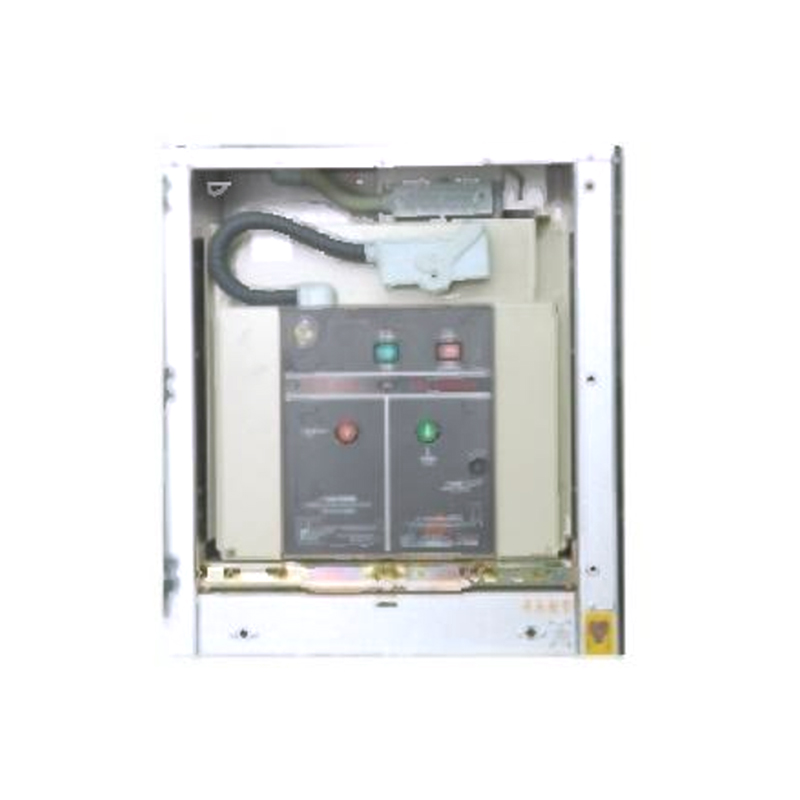 24kV Armored Removable Metal-Enclosed SwitchgearThis switchgear features an assembled structure, securely connected by high-strength bolts and rivet nuts. To ensure operational safety, the main switch, handcart, and...View Product →
The nameplate is a short document, and every field on it exists because it changes the measurement.
| Class | Typical duty | What it means in practice |
|---|---|---|
| 0.1 / 0.2 / 0.2S | Laboratory and high accuracy metering | Tightest errors at rated current; the S version stays accurate down to a few percent of rated current |
| 0.5 / 0.5S | Revenue metering | The usual choice for billing points and utility metering |
| 1 / 3 | Panel instruments | Acceptable for indication and internal energy tracking |
| 5P / 10P | Overcurrent protection | Composite error of 5 or 10 percent at the accuracy limit factor, for example 5P10 |
| PX / PS | Differential protection | Defined by knee point voltage, excitation current and secondary resistance rather than a class number |
Three more values deserve attention. The accuracy limit factor tells you how many times rated current a protection core can carry before its error passes the stated limit. The instrument security factor tells you how far a metering core can be overloaded before accuracy is lost, and a low factor protects the meter. The rated continuous thermal current, usually 1.2 times rated, sets the thermal ceiling, while the short-time thermal current and its duration describe what the CT can survive during a fault.
A CT secondary normally operates close to a short circuit, with only a few volts across it. Open that circuit while primary current flows and the balance changes instantly: with no secondary ampere-turns to oppose the primary magnetomotive force, the entire primary current becomes excitation current. The core saturates hard, the flux changes very quickly, and a steep voltage spike appears across the open terminals. That spike can reach kilovolts, enough to puncture insulation, strike an arc and expose anyone nearby to a serious shock, and the core and winding can be destroyed by heating.
Both are instrument transformers, and both exist to give instruments a safe, scaled copy of a primary quantity. They behave in opposite ways.
| Characteristic | Current transformer | Voltage transformer |
|---|---|---|
| Primary connection | In series with the load conductor | In parallel with the measured circuit |
| Secondary output | Current, normally 1 A or 5 A | Voltage, normally 100 V to 120 V |
| Normal secondary condition | Near short circuit, low impedance burden | Near open circuit, high impedance burden |
| Condition to avoid | An open secondary | A short circuited secondary |
| Quantity tracked | Current | Voltage |
CTs appear wherever current has to be measured safely or acted upon quickly.
In a ring main unit, a packaged substation or a compact distribution room, the CTs are integrated into the switchgear rather than bought as loose components, because the window, mounting and wiring are part of the panel design.
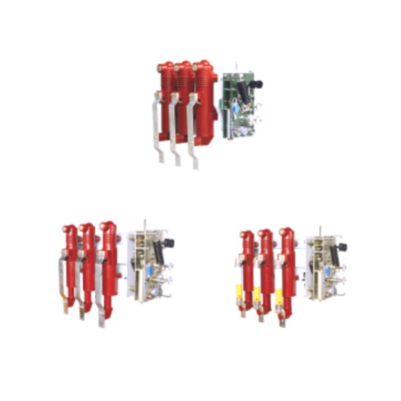 Indoor AC Metal Enclosed Ring Network Switch EquipmentThis product features advanced composite insulation technology, providing resistance to ultraviolet rays, anti-aging properties, high strength, and electrical insulati...View Product →
Most specification mistakes come from treating the CT as an isolated part. In practice, the CT inside a panel, the panel itself and the transformer it protects are one electrical system. A large cast resin transformer and a feeder relay see the same fault, so the instrument transformers and the protection settings must be coordinated rather than selected separately.
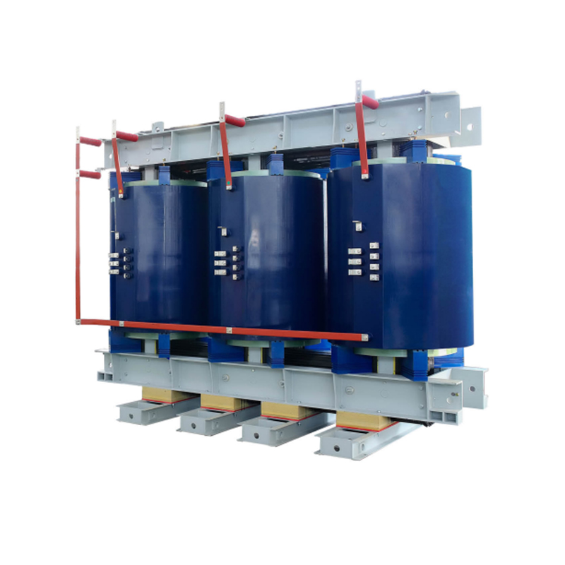 Epoxy Resin Cast Dry Type Transformer - 800 to 25000 kVAFor this SC10-800~2500 series epoxy resin cast dry type transformers, both high and low voltage windings utilize an advanced vacuum pressure resin casting process. Thi...View Product →
A current transformer definition, in the end, is a promise: measure the primary current faithfully, isolate the people and instruments downstream, and stay predictable when a fault arrives. Ratio, class, burden, window size and insulation are simply the details through which that promise is kept in a particular switchboard.
Detong Transformer builds the medium-voltage equipment in which that promise is kept every day. Our range covers cast resin dry-type transformers, oil-immersed power and distribution transformers, iron-core reactors, armored switchgear, ring main units and prefabricated substations, all engineered for coordinated use in the same distribution system. If you are defining instrument transformer and protection requirements for an upcoming project, our engineers are glad to help match the pieces into one dependable package.
1.Types of High Voltage Switchgear The main categories of high voltage switchgear include Air-Insula...
View More1. Working Principle Oil-immersed transformers play a pivotal role in modern electrical power system...
View More1. Advantages of Distribution Dry Type Transformers Distribution dry type transformers have become i...
View More
 中文简体
中文简体 русский
 Español
 عربى
عربى