
Get a Quote


Walk into almost any distribution or transmission substation and the first things you notice are the big items: power transformers, circuit breakers, busbars, steel structures. Current transformers are easy to overlook. They are the rings clamped around a cable, the stacked cores inside a switchgear cubicle, or the small tank mounted on a post insulator. Yet nearly every protection trip and every kilowatt-hour figure that leaves that substation depends on them.
At Zhejiang Detong Transformer, we build dry-type transformers, oil-immersed transformers, reactors, and switchgear for substations and industrial power systems, so we spend a lot of time on the interface between that equipment and the instrument transformers measuring it. This article covers what current transformers in substations actually do, how the main types differ, how accuracy classes should be read, and which practical details cause the most trouble on site.
A current transformer, or CT, scales a large primary current down to a small, safe secondary current that relays, meters, and remote terminals can read. The relationship is set by the turns ratio: a 600/5 CT with a single primary turn and 120 secondary turns produces 5 A of secondary current when 600 A flows in the primary conductor. Standard secondary ratings are 1 A and 5 A, and the choice between them is a system decision rather than a CT decision.
Two functions are bundled into that simple description. The first is measurement: turning an unreadable primary current into something a meter can log accurately. The second is isolation: keeping several hundred or several thousand volts away from a panel a technician may open by hand. Both matter, and both depend on treating the CT as part of the protection system rather than as a passive accessory.
Safety follows from the same physics. A CT with an open secondary has nowhere for its magnetising current to go, so voltage across the secondary terminals rises sharply. That is why shorting links are fitted at test blocks, and why secondary circuits must never be opened under load.
Bushing current transformers slide over the bushings of power transformers, circuit breakers, or cable terminations, saving space and cost in high-voltage bays. Toroidal CTs wrap a core around a single conductor and are popular in medium-voltage switchgear. Core-balance CTs, sometimes called CBCTs, sum the three phase currents inside one core so any residual current produces an output — the basis of sensitive earth-fault protection on feeders and cable circuits.
Indoor units are usually cast in epoxy resin, which is self-supporting, moisture resistant, and effectively maintenance free. Outdoor and higher-voltage CTs are more often oil insulated or gas insulated, with porcelain or composite housings and an oil-level or gas-density arrangement that requires periodic checks. The environment, not the ratio, usually decides which family you end up specifying.
Metering CTs and protection CTs are built to different targets, and mixing them up is one of the most common specification errors we see. A metering class CT is optimised for small errors near rated current. A protection class CT is optimised for staying reasonably accurate when fault current is many times rated current.
| Class | Typical duty | What the marking tells you |
|---|---|---|
| 0.2 / 0.2S | Revenue metering | Very small ratio and phase error, with 0.2S extended to low currents |
| 0.5 / 0.5S | Sub-metering and monitoring | Commercial metering accuracy at rated burden |
| 1.0 / 3.0 | Indicating instruments | Loose accuracy, not suitable for billing |
| 5P / 10P | Overcurrent protection | Composite error limit at the stated accuracy limit factor |
| 5P20 / 10P10 | Feeder and transformer protection | Stated accuracy held up to 20 or 10 times rated current |
| PX / PS / TPX | Differential and unit schemes | Knee point, magnetising current, and secondary resistance defined |
Two numbers travel with every protection class. The accuracy limit factor, or ALF, says how many times rated current the CT can carry while staying inside its composite error limit. The burden, expressed in volt-amperes at a stated power factor, says how much connected load the CT can drive. Relays with low-burden inputs made life easier, but adding a second relay, a transducer, or long secondary cables quickly uses up the allowance.
Saturation is the practical consequence of ignoring that balance. When the core saturates, secondary current stops following primary current, and a differential relay may see a fault that is not there — or miss one that is. A higher ALF, a larger core, or a lower-burden relay is usually cheaper than discovering the problem during commissioning.
In medium-voltage substations, most CTs are inside switchgear. A metal-enclosed cubicle typically carries three phase CTs on the feeder side, a core-balance CT around the cable gland, and often a set of CTs on the incomer for metering. Space, cable termination height, and the short-circuit rating of the enclosure all constrain what will physically fit.
That is why the switchgear and the instrument transformers should be selected together rather than in separate packages. If you want a closer look at how the enclosure side of the equation works, our guide to high-voltage switchgear types and applications walks through the main configurations.
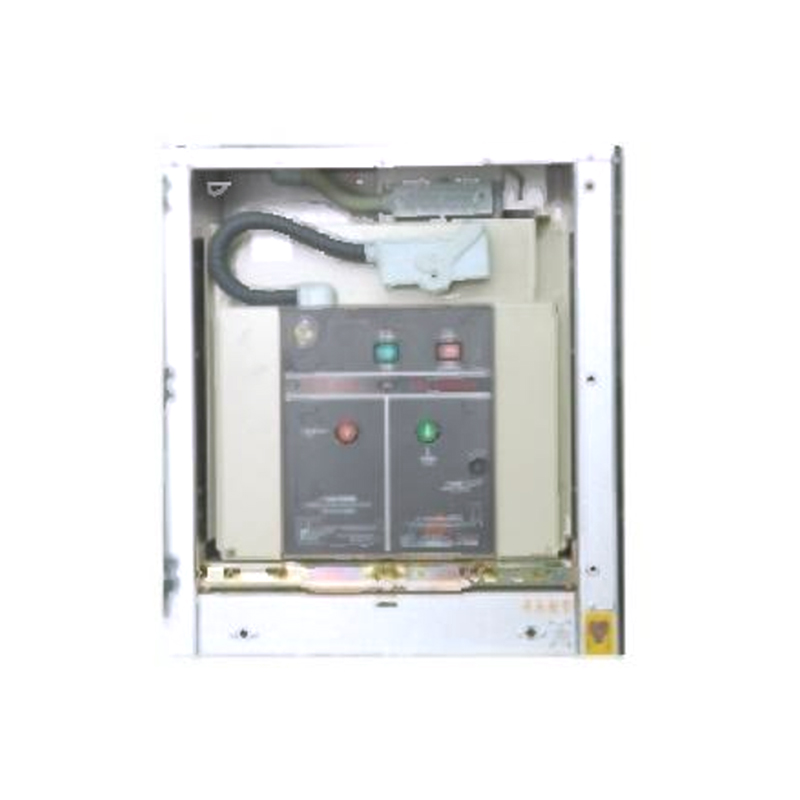 24kV Armored Removable Metal-Enclosed SwitchgearThis switchgear features an assembled structure, securely connected by high-strength bolts and rivet nuts. To ensure operational safety, the main switch, handcart, and...View Product →
For 24 kV distribution systems, an armored removable metal-enclosed cubicle provides draw-out breakers, dedicated CT compartments, and a defined earthing path — a combination that keeps CT replacement a planned maintenance job rather than an outage emergency.
On the power transformer itself, CTs are frequently built into the bushings or mounted in a separate turret, feeding differential protection, overcurrent backup, and metering. Ratio selection should follow the transformer's rated current and the expected fault level, not the other way round. A 35 kV transformer with a 20 MVA rating will need a different CT ratio set than a small distribution unit on the same network.
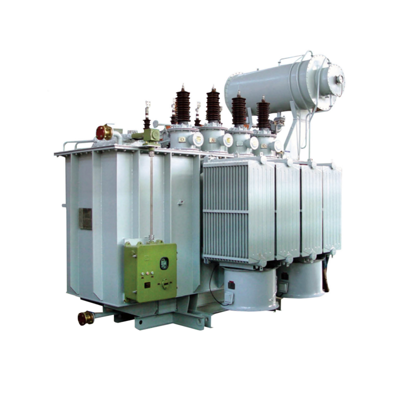 35kV Oil Immersed Power Transformer - 630 to 31500 kVAIn terms of design, we prioritize the use of copper foil for low-voltage windings, while the high-voltage coils feature a multi-layer cylindrical structure. Axial oil ...View Product →
For outdoor 35 kV substations, pairing oil-immersed power transformers with correctly rated bushing CTs keeps the differential zone simple and the secondary wiring short. Where the substation sits indoors, in a basement, or inside a plant building, the picture changes.
Indoor substations bring fire load and ventilation into the specification. A cast-resin dry-type transformer removes the oil, keeps the CT wiring in a clean, dry environment, and simplifies the cable route to the switchgear.
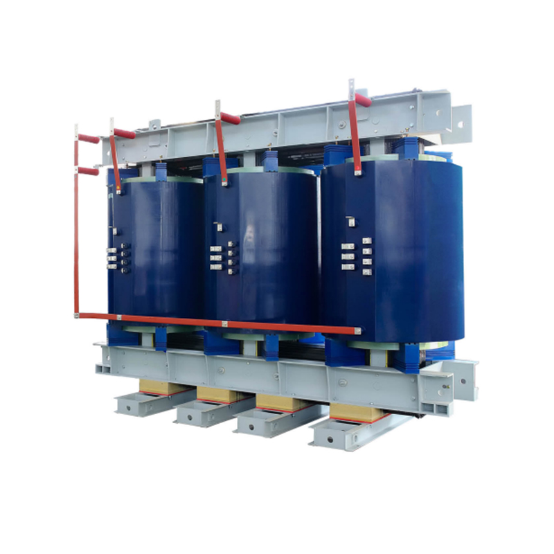 Epoxy Resin Cast Dry Type Transformer - 800 to 25000 kVAFor this SC10-800~2500 series epoxy resin cast dry type transformers, both high and low voltage windings utilize an advanced vacuum pressure resin casting process. Thi...View Product →
Once the equipment is on site, a handful of checks decide whether the CT installation will behave for the next twenty years.
Commissioning is also the last chance to catch a mismatch between the CT class and the relay settings. If a 5P20 core has been applied to a scheme that expects a defined knee point, no amount of setting adjustment will fix the saturation behaviour.
Current transformers in substations rarely attract attention on a single-line diagram, but they set the ceiling for how well the protection scheme can work. Treating them as an engineered part of the bay — chosen alongside the switchgear, the relay, and the power transformer — is the simplest way to avoid surprises at commissioning.
1.Types of High Voltage Switchgear The main categories of high voltage switchgear include Air-Insula...
View More1. Working Principle Oil-immersed transformers play a pivotal role in modern electrical power system...
View More1. Advantages of Distribution Dry Type Transformers Distribution dry type transformers have become i...
View More
 中文简体
中文简体 русский
 Español
 عربى
عربى